

In this phase we will define the behavior of turbines with a statechart: when and how they get out of service or get scheduled maintenance. Also, we will set up the turbine animation: we want the blades to stop rotating when a turbine is out of service; moreover, every turbine animation figure has color indicators of its turbine state.
Set up time intervals on the turbine agent type
- Double-click
 Turbine in the model tree to open its diagram. Start with adding two
 Parameter elements from the
 Agent palette into the graphical editor.
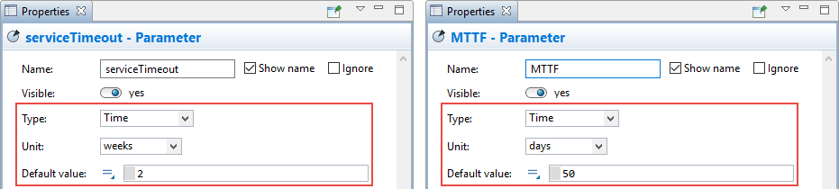
 - The parameter called serviceTimeout is of type Time and its Default value is 2 weeks (select weeks in the Units property).
- The second parameter, MTTF (mean time to failure), is also of type Time and its Default value is 50 days.
Set up the function managing requests for transport
- Add a
 Function from the
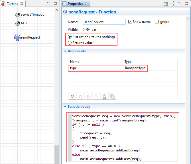
Agent palette and name it sendRequest. This function is Just action and it has one argument you can set up in the properties section Arguments: TransportType type. In the function body we call the function findTransport that we have created on
Main. When a turbine sends a service request, the maintenance center should send transport of a specified type, AUTO or AVIA.
Function from the
Agent palette and name it sendRequest. This function is Just action and it has one argument you can set up in the properties section Arguments: TransportType type. In the function body we call the function findTransport that we have created on
Main. When a turbine sends a service request, the maintenance center should send transport of a specified type, AUTO or AVIA.
Define the turbines behavior with the statechart
- Now we are ready to create a statechart. Open the
 Statechart palette and drag and drop into
Turbine diagram the
Statechart palette and drag and drop into
Turbine diagram the
 Statechart Entry Point element.
 - Connect a
 State to the statechart entry point, name it Operating. Increase the state size since we want it to act as a composite state containing two simple states inside. Into the Operating state, add
 Initial State Pointer, then continue with drawing the remaining states, connecting them together with transitions and configuring the transitions as shown in the figure below. Additionally, you can resize the statechart elements and set some custom colors for the states.

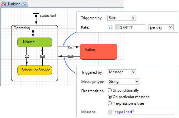
- Each turbine state has its own Entry action. When a turbine needs repair, it is in the
Failure state sending a maintenance request for AVIA transport (a helicopter). When it is time for the scheduled service, a turbine sends a request for AUTO type of transport — a truck.
State Entry action Failure sendRequest(AVIA); ScheduledService sendRequest(AUTO); - The transition from
Operating state to
Failure is triggered by
 Rate that equals 1/MTTF per day — once in the mean time to failure period. The transition that goes back from
Failure to
Operating state is triggered by a
Rate that equals 1/MTTF per day — once in the mean time to failure period. The transition that goes back from
Failure to
Operating state is triggered by a  particular message — "repaired".
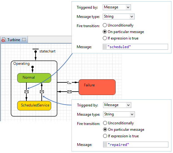
- When an operating turbine receives a message "scheduled", it means, a turbine needs scheduled service and the corresponding state is triggered. Being in
ScheduledService state, when a turbine receives a message "repaired", the service is finished, and it can get back to the Operating state.
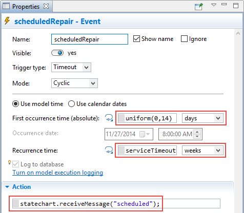
-
Add a cyclic timeout
 Event called scheduledRepair. This event will happen when a turbine needs a scheduled maintenance (according to
serviceTimeout) that triggers the transition from
Operating state to
ScheduledService.
Event called scheduledRepair. This event will happen when a turbine needs a scheduled maintenance (according to
serviceTimeout) that triggers the transition from
Operating state to
ScheduledService.
Change animation of the turbine blades
- We need to change the properties of the turbine blades. The Wind turbine rotating figure is actually a group consisting of 2 3D figures: turbine tower and turbine blades. We need to open the properties of the blades.
- You can select the blades with a mouse click in the graphical editor, or open the Projects view and keep expanding the model tree levels until you get to the wind_blades group.
- Go to its properties. Open the section Position and size and type inState(Operating)?time():0 in the property Rotation Y, rad. Now the blades will be rotating when the turbine is working, and when it is out of service and needs repair the blades will remain still.

Create the turbine state indicator
- Open the
 Presentation palette and double-click the
 Oval element to enable the drawing mode.
 - Draw a circle around the turbine animation figure with the radius 25.
- Right-click the circle and select Order > Send to Back from the context menu.
- Go to the Appearance section of the circle properties. Enter the expression that will be evaluated during the run-time for the Fill color to make it change according to the turbine state.
- In order to switch to dynamic value mode for the property, click its icon
 .
.
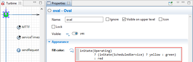
- If a turbine is waiting for service the shape displays the yellow color, otherwise the circle is green which is the indicator for a working turbine, and if it is out of service the indicator displays the red color.
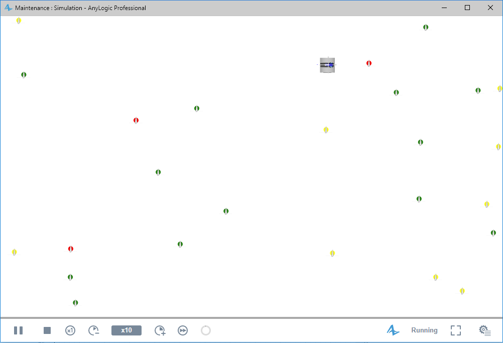
Run the model now. You will see that some turbines are working, some are waiting for the scheduled maintenance and some turbines need urgent repair.
Now we are ready to define the transport movement.
-
How can we improve this article?
-