

In AnyLogic, you define stairs connecting two floors using nodes, see the demo model below.
Demo model: Stairs Open the model page in AnyLogic Cloud. There you can run the model or download it (by clicking Model source files). Demo model: StairsOpen the model in your AnyLogic desktop installation.Let’s explain how you can bring the same logic into your model.
Usually when you develop a pedestrian model, you have a layout of the simulated building (station, museum, stadium, etc.).
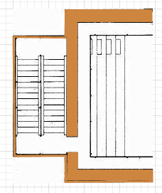
First, you need to draw the area and place it exactly over the stairs area on the drawing.
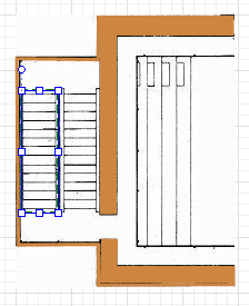
Draw the stairs area
- Drag the Rectangular Node
 element from the Markup section of the Pedestrian Library palette onto the graphical editor, over the layout.
 - Resize the node as you need. Finally it should lie exactly over the stairs area on the drawing.
The next thing we need to do is define the slope angle for this node.
Define a slope for the area
- To make the node sloped, first select the Slope for pedestrians option in the node’s Position and size properties.
- You will see the slope line appeared inside the node in the graphical editor:
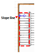
- In the graphical editor, adjust the slope line’s direction. The line should point exactly in the Z-coordinates growth direction.
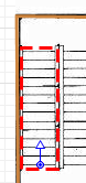
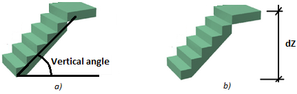
- Now we need to define the stairs slope itself. Usually you know either stairs slope angle (case a on the figure below), or the height between the levels (case b).
- Click the slope line and tune it to define the required slope.
- If you know the angle value (case a), leave Define slope as: angle option selected and specify the angle value in the Vertical angle control below.
- Otherwise, if you know the height between the levels (case b), choose guiding line in the slope line’s Define slope as property. In the dZ property below, enter the height between the levels, in pixels. Then direct the slope line in the graphical editor so that in XY plane it lies parallel to the stairs area direction.
-
How can we improve this article?
-