

In the previous phase we created a new model, populated it with facilities, defined animation shapes for the facilities, added 3D view and camera to observe the running model and finally added protected area.
In this phase we will add bomber aircrafts to our model, define their behavior and mission.
Let us start with creating a new population of agents that will represent the bombers.
Create a new agent type
- Drag the
 Agent element from the
 Agent palette onto the
Main diagram. Place it nearby the
buildings population to the left of the model animation.
Agent palette onto the
Main diagram. Place it nearby the
buildings population to the left of the model animation. - Click Population of agents. You will be taken to the next step.
- Specify Bomber in the Agent type name field on the third step of the agent wizard. Click Next.
- Choose the Bomber animation shape in the Military section. Click Next.
- Define the population’s parameter:
- Click add new... to create a parameter.
- Type target into the Parameter field.
- Set Type to Other (additional drop-down list will appear next to it).
- Select Building from the additional drop-down list of the parameter’s type (This will be the target building in the bomber mission).
Click Next.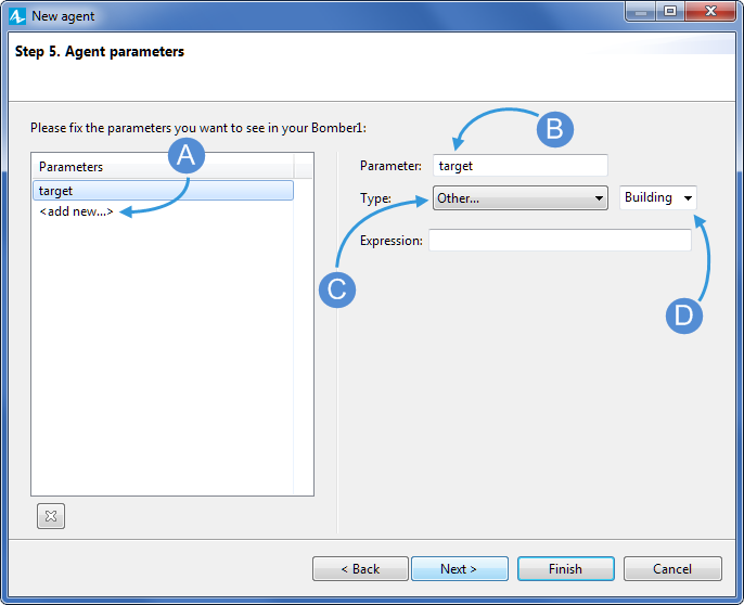
- Select the Create initially empty population, I will add agents at the model runtime option.
- Finally, click Finish.
Now we will define the coordinates of the bombers' initial location.
Define initial location
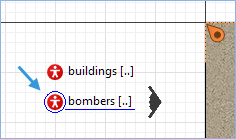
- Click the
bombers population element to open its properties.
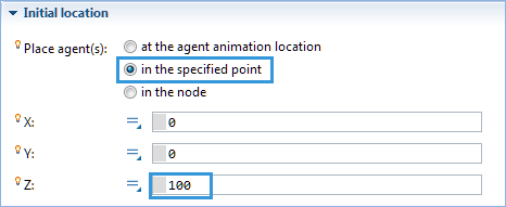
-
Navigate to the Initial position section of the element’s Properties, set its Place agent(s) parameter to in the specified point to manually specify the point of appearance and then type 100 into the Z coordinate’s field to specify the altitude at which the bombers will be flying into the scene.
The next step is to define the velocity of the aircraft. It is done right here, in the same Properties view, just above the Initial position section.
Define the velocity of the aircraft
- Navigate to the Dimensions and movement section and set the Initial speed parameter to 600, then click the speed units drop-down menu to the right of it and select kilometers per hour.
Now that we have created bombers and defined their animation, initial location and target, we can move on to create the initial version of their behavior using the statechart.
Once created, the bombers will be heading towards the buildings (it is set by the target parameter). We will now define the further behavior, which will make the bombers gradually get to a lower altitude and then return to the initial point where they will delete themselves from the model.
Create the behavior defining statechart
- Double-click
Bomber in the Projects view to open its diagram.
- Switch to the
Agent palette to use its statechart section.
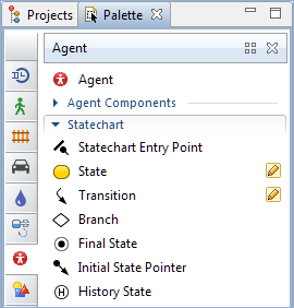
- Drag the
 Statechart Entry Point element to the graphical editor of the
Bomber agent.
Statechart Entry Point element to the graphical editor of the
Bomber agent.
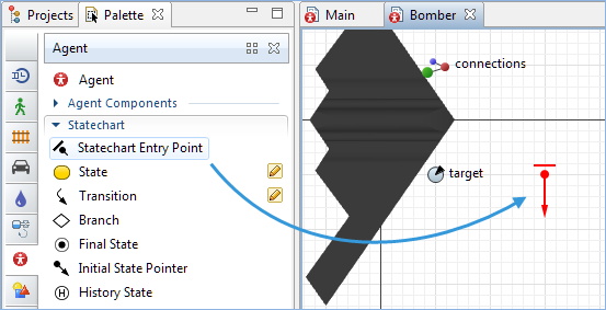
- Double-click the
 State element to activate the drawing mode and draw a state rectangle below the previously drawn
Statechart Entry Point.
State element to activate the drawing mode and draw a state rectangle below the previously drawn
Statechart Entry Point. - Name it ToTarget and drag it up to the entry point until you see the green dot indicating that the two elements can be connected.
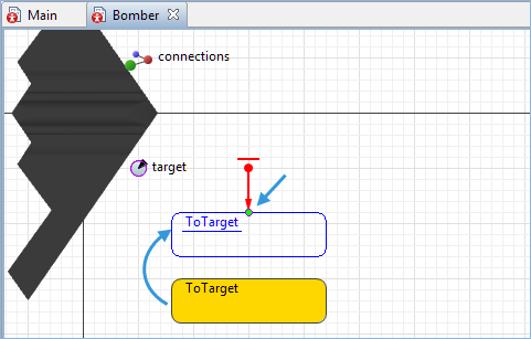 You can alternatively simply click and drag the State element from the palette directly to the
Statechart Entry Point element located on the
Bomber diagram. The automatically drawn element can be later resized if needed.
You can alternatively simply click and drag the State element from the palette directly to the
Statechart Entry Point element located on the
Bomber diagram. The automatically drawn element can be later resized if needed. -
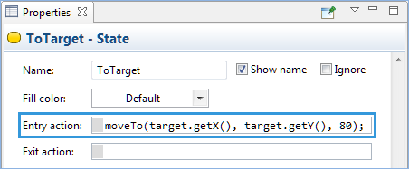
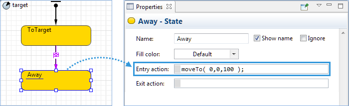
Modify the Entry action field in the Properties view of the
ToTarget state. Type in the following code to define the coordinates of the bombers’ location. By specifying the code we will define the altitude different from the one specified in the Initial position section. It will make the bombers get to a lower altitude on their way to the targets, which are represented in our case by the buildings.
When typing Java code, use Code completion master, accessible by clicking Ctrl + space (macOS: Alt + space) in the code field. It provides you with the list of available functions and model elements, so you can simply choose the required item from the list and avoid mistypes when referring to it.
-
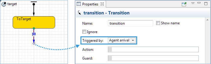
Drag the
 Transition element to the
ToTarget state on the
diagram and connect them. Then navigate to its properties and set the Triggered by parameter to Agent arrival.
Transition element to the
ToTarget state on the
diagram and connect them. Then navigate to its properties and set the Triggered by parameter to Agent arrival.
-
Now drag another
State element to the agent diagram and connect it to the
Transition element. Name it Away. Then navigate to its Properties view and type the following code into the Entry action field, which will make the bombers get back to their previous altitude once they have reached their targets.
- Drag another
Transition element to the agent diagram and connect it to the
Away element. Then navigate to its properties and set the Triggered by parameter to Agent arrival. The two transition elements on the statechart diagram must be identical.
-
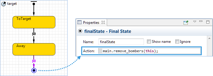
Finally, drag the
 Final State element to the agent diagram and connect it to the last added
Transition element. Then navigate to its Properties view and type the following code into the Entry action field, which will remove the bombers that have completed all the steps of this statechart.
Final State element to the agent diagram and connect it to the last added
Transition element. Then navigate to its Properties view and type the following code into the Entry action field, which will remove the bombers that have completed all the steps of this statechart.
We have completed the behavior defining statechart. As you can see we call the moveTo() function in the On enter field of both states to initiate movement of the agent. The transition from one state to another is triggered by the agent arrival. This pattern is very common in the agent based models.
The next step is to create the mission assignment. We will do it with the help of the
 Event element.
Program mission assignment
- Switch to the
Main diagram of the top level agent.
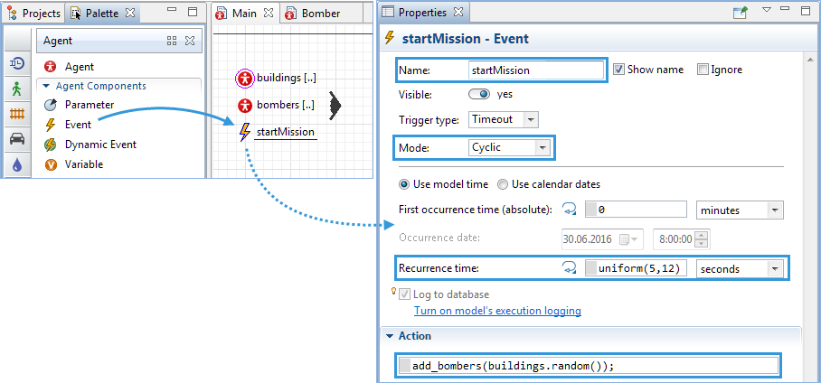
- Drag the
Event element from the Agent palette to the
Main diagram and place it beside the agents populations.
- Navigate to its Properties and perform the following changes:
- Name it startMission.
- Set the Mode parameter to Cyclic.
- Set the Recurrence time parameter’s time units to seconds and type uniform(5,12) into the parameter’s field.
- Type add_bombers(buildings.random()); into the field of the Action section.
Bomber agent has one parameter target of type
Building, AnyLogic generates a constructor with that parameter).
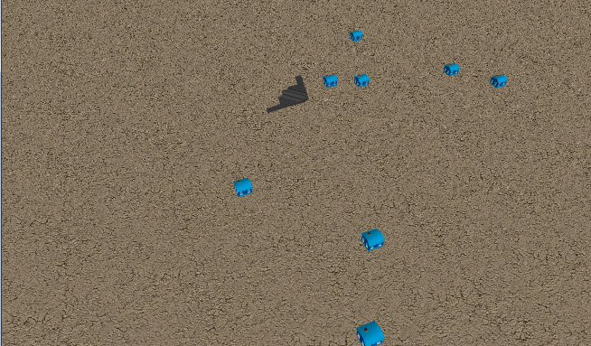
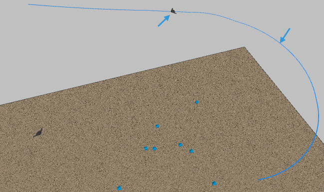
Finally, we can run the model to observe the flight of the bombers live.
Upon creation, a bomber takes direction to the target building, makes an “instant u-turn”, and heads back to (0,0). So far, the bombers use straight line trajectories — this is assumed by the moveTo( x, y, z ) function. We will further draw the 3D “escape trajectory” for the return route and set the bombers to follow that trajectory on their way back. We will use another version of the method: moveTo( main.exitNode );.
Now we will create escape route that the aircrafts will be following to avoid being hit by a missile.
Draw the 3D escape route
-
Open the Space Markup palette, double-click the
 Path element to activate the editing mode and draw a path, as shown in the figure.
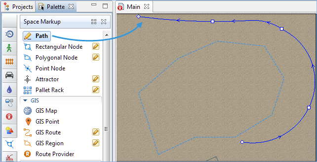
- Navigate to its properties and name the path escapeRoute.
- Set the Z parameter of the Position section to 100 (this will be the base Z-coordinate of the polyline).
-
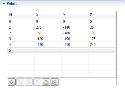
Open the Points section of the path properties and modify the individual Z coordinates of the points approximately, as shown in the figure. The idea is to have the initial section of the path at about the same altitude as the bomber attack altitude.
- Add
 Point Node from the Space Markup palette to the end of the path, make sure the node connects to the path. Name it exitNode. Set its Z parameter of the Position and size section to 340.
 -
Open the diagram of the
Bomber agent, click the Away state to navigate to its properties and change the Entry action to: moveTo( main.exitNode );
We need to put the prefix main before the exitNode because this graphical object is located not inside the Bomber agent, but one level up, in
Main.
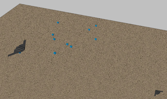
Run the model. See how the bombers return to the base using the defined by the path route.
The escapeRoute is visible at runtime. We will now set the Visible parameter of both the escapeRoute and the exitNode to no, to hide both of them.
Hide escapeRoute during runtime
- Click the escapeRoute to select it.
- Navigate to its Properties view and click the Visible parameter’s toggle button to switch the visualization state to no. The escapeRoute will not be visible during runtime now.
In the same way hide the exitNode.
Run the model. No odd elements are present in the scene now.
We have completed the second phase of the Air defense system tutorial.
Demo model: Air Defense System — Phase 2 Open the model page in AnyLogic Cloud. There you can run the model or download it (by clicking Model source files). Demo model: Air Defense System — Phase 2Open the model in your AnyLogic desktop installation.-
How can we improve this article?
-