

In the course of the previous phases we have modeled the battery production process with a single electrode type. In reality the battery contains the electrodes of two types: anode (negative) and cathode (positive). The preparation processes for these two types are similar enough that they both could be described by the electrode preparation logic we employ in our model. To avoid the duplication of the existing block sequence and make our flowchart concise, we will create a custom block that encapsulates this sequence and use parameters to distinguish between the anode preparation process and cathode preparation process.
But first, we will draw the missing section of the production floor layout where the cathodes are handled.
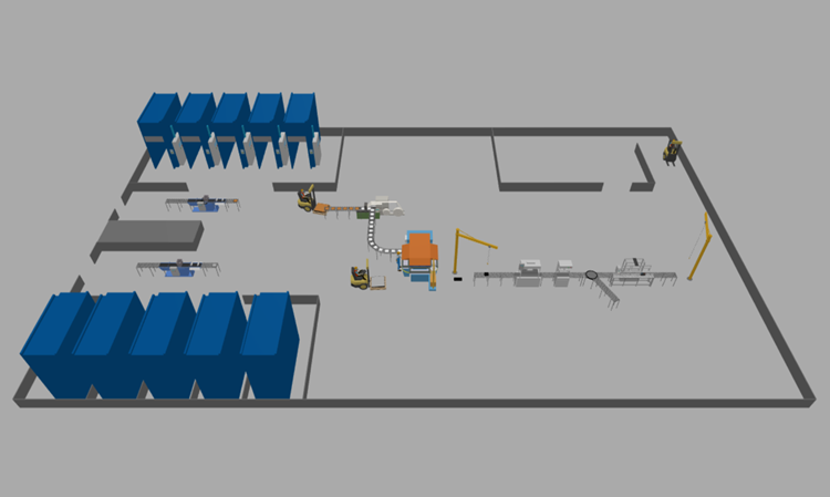
Prepare the layout
-
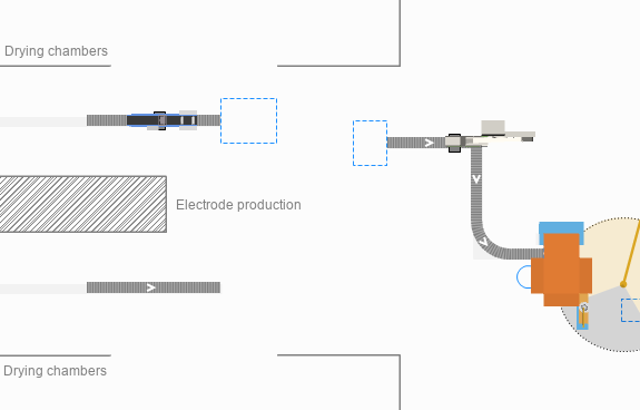
Draw a conveyor as displayed in the image below and name it cathodeConveyor.
-
In its properties specify the following:
-
Material item type:
 Electrode
- Z: 20
- Width: 0.5 meter
-
Material item type:
- Place a
 Station on the
 cathodeConveyor.
 - Name it cathodeCoatingStation.
-
In its properties specify:
- Visible: no
- Process time: 1 second
- Length: 0.5 meter
-
In the Actions section of the station’s properties type the following code in the On process finished field: agent.color = silver;.
We use this code to change the color of the cathode plates passing through the coating station. - Using the
 Rectangular Node element from the
 Space Markup palette, draw the area at the end of the
cathodeConveyor where the coated cathodes will be stored.
Space Markup palette, draw the area at the end of the
cathodeConveyor where the coated cathodes will be stored. - Name it cathodePlatesBuffer.
-
In the node’s properties specify:
- Visible: no
- Locations layout: Arranged
- Next, draw the location where the cathodes will be transported for curing.
- Name it cathodeCuringOven.
- In the properties of the
cathodeCuringOven set the Visible property to no.
-
Next, click Attractors…. In the dialog that appears, specify the attractors creation mode as a grid of 5 x 1.
- Draw another
Rectangular Node.
- Name it preassembleCathodesBuffer.
-
Set the Visible property to no and the Locations layout to Arranged.
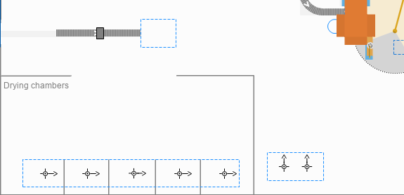
Add the 3D animation
- Go to the
 3D Objects palette and drag the Pasting Machine 3D object to the
Main diagram.
3D Objects palette and drag the Pasting Machine 3D object to the
Main diagram. - In the Auto scale 3D object dialog that appears, click Yes.
- Place it over the
cathodeConveyor..
- Drag the Drying Chamber 3D object and place it over the attractor in the
cathodeCuringOven node.
- In the Auto scale 3D object dialog that appears, click Yes.
- Make sure that the figure is located inside the walls of the layout and completely covers the attractor. Note that you can also adjust the placement of attractors in the node by selecting and dragging them.
- Rotate the figure using the handle so that the entrance to the curing chamber is facing the
cathodeConveyor.
-
Hold down Ctrl and drag the Drying Chamber 3D figure to create 4 more copies and adjust their placement as shown in the figure below.
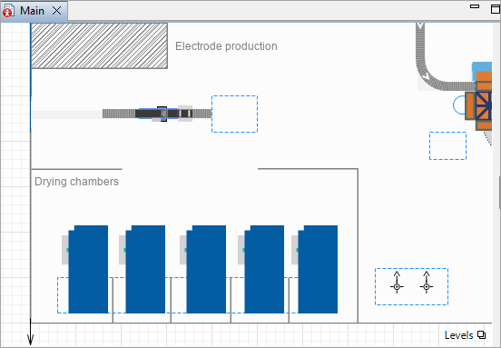
Now that the layout and animation are ready, we can start making changes in the flowchart.
Create a custom block
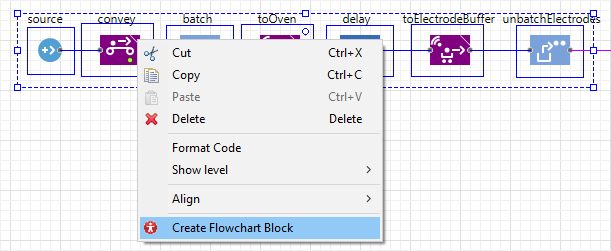
- Select the first seven blocks of the flowchart (from the source block to the unbatchElectrodes block) and right-click the selection.
-
Select the Create Flowchart Block option from the context menu.
- In the displayed New agent dialog window specify the Name: PrepareElectrode.
- A new block prepareElectrode with a default icon will replace the selected blocks in the flowchart.
- The
PrepareElectrode agent will appear in the model tree in the
 Projects view.
If you select the prepareElectrode block in the graphical editor, in its properties you will see all the customized parameters of the initial seven blocks. The labels of the parameters are generated automatically. Our next step will be to correct these labels and adjust the parameters themselves.
Correct the parameter labels of the custom block
- Double-click the
PrepareElectrode agent in the
Projects view to open its graphical editor. You can see all the parameters located on the agent’s graphical diagram.
-
To change the parameter’s label, select the parameter, go to the Value editor section of its properties and type the new label in the Label field.
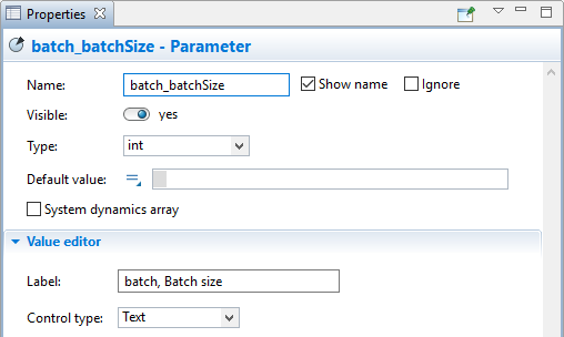
-
Use this method to change the parameter’s labels according to the table below.
You will see that not all parameters are listed in the table. Do not worry and skip the unlisted ones, since they will be adjusted separately.
Parameter name New label batch_batchSize Batch size batch_EntityLocation Location of plates for batching batch_LocationNode Batch location convey_sourceConveyor Electrodes source conveyor convey_targetConveyor Electrodes target conveyor delay_delayTime Curing time source_entitiesPerArrival Electrodes per arrival source_interarrivalTime Electrodes interarrival time toElectrodeBuffer_destinationNode Electrodes buffer toElectrodeBuffer_loadingTime Time to load at the oven toElectrodeBuffer_unloadingTime Time to unload at the buffer toOven_destinationNode Curing oven toOven_fleet Forklifts fleet toOven_loadingTime Time to load batch from the conveyor toOven_unloadingTime Time to unload batch at the oven unbatchElectrodes_locationX Unbatched electrodes location, X unbatchElectrodes_locationY Unbatched electrodes location, Y
Next, we must deal with the remaining parameters.
Adjust the custom block’s parameters
-
Since in our model both anodes and cathodes are represented by the
Electrode agent, go to the source block's properties, switch the New agent field back to the value editor mode and select
Electrode from the drop-down list.
-
Delete the
 source_newEntity parameter.
-
Similarly, both anode and cathode batches will be represented by the
PlatesBatch agent. Go to the batch block properties, switch the New batch field back to value editor mode and select the
PlatesBatch agent from the drop-down list.
- Delete the
batch_newBatch parameter.
- Both anodes and cathodes batches will be transported by the same fleet, therefore go to the toElectrodeBuffer block’s properties and specify the Fleet: toOven_fleet(agent).
- Delete the
toElectrodeBuffer_fleet parameter from the
PrepareElectrode graphical editor.
Now that we have finished adjusting the parameters, let’s change the default icon of our custom block to the following figure: ![]() .
.
- Right-click the suggested block figure above, select Save Image As from the context menu, and save the figure to your model folder.
-
Delete the blue rectangle in the
PrepareElectrode graphical editor.
To do this, click the rectangle on the graphical diagram and then press Delete on your keyboard.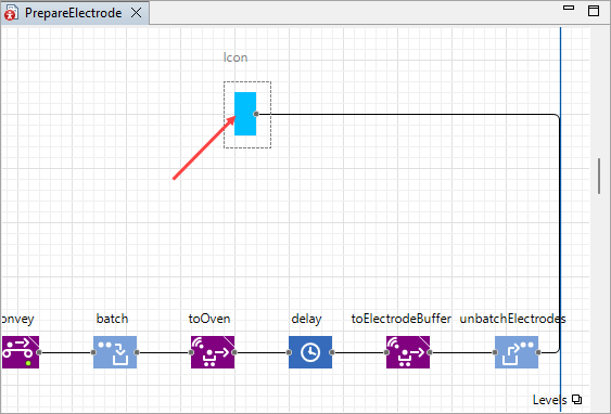
- Drag the
 Image element from the
 Presentation palette to the graphical diagram of the
PrepareElectrode agent and place it roughly over the icon area where the blue rectangle used to be.
Presentation palette to the graphical diagram of the
PrepareElectrode agent and place it roughly over the icon area where the blue rectangle used to be. - In the window that appears, navigate to the model folder and select the saved custom icon figure.
- The properties of the image will automatically open. Select the Icon check box.
-
Adjust the placement of the icon so that the port is situated exactly at the edge of the figure:

-
Navigate to the Advanced section of the icon’s properties and enter the following code in the On click field:
return true;
This will allow us to navigate inside the custom block by double-clicking it during the simulation. -
We should also add the counter to see how many agents have been generated by this block.
Drag the Text element from the
Presentation palette and place it next to the right bottom corner of the new icon.
Text element from the
Presentation palette and place it next to the right bottom corner of the new icon.
-
In the properties of the
Text element, do the following:
- Select the Icon check box.
- In the Text field type a stub value: for example, 0.
- Next, switch the field to the dynamic value editor by clicking the icon to the left. In the edit box, type the following expression:
source.out.count()
- Set the Color to blue.
Add the logic behind the cathodes preparation process
- Go to the
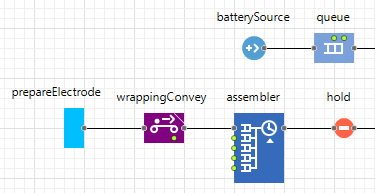
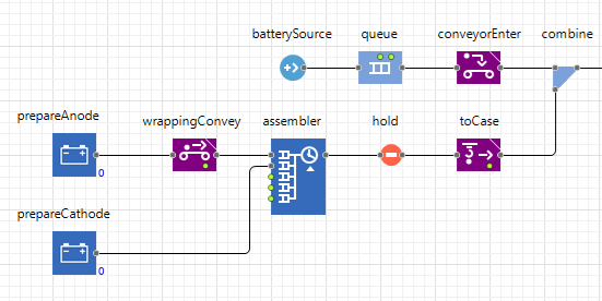
Main graphical diagram and rename the prepareElectrode block to prepareAnode.
-
Drag the
PrepareElectrode element from the model tree to the
Main diagram and connect it to the second in port of the assembler block. Name the block prepareCathode.
-
In the block’s properties specify the following:
- Batch size: 100
- Location of plates for batching:
cathodePlatesBuffer
- Batch location:
cathodePlatesBuffer
- Electrodes source conveyor:
cathodeConveyor
- Electrodes target conveyor:
cathodeConveyor
- Curing time: 2 minutes
- Curing location:
cathodeCuringOven
- Electrodes per arrival: 200
- Electrodes interarrival time: 1.5 hours
- Electrodes buffer:
preassembleCathodesBuffer
- Time to load at the oven: 0.5 minutes
- Time to unload at the buffer: 0.5 minutes
- Curing oven:
cathodeCuringOven
- Forklifts fleet:
 forklifts
 - Time to load batch from the conveyor: 0.5 minutes
- Time to unload batch at the oven: 0.5 minutes
- Unbatched electrodes location, X: wrappingConveyor.getEndPoint().x
- Unbatched electrodes location, Y: wrappingConveyor.getEndPoint().y
The unbatched cathodes should appear on the same wrappingConveyor, but the exact location is the end point of the conveyor. To obtain the x- and y-coordinate of this point, we use the getEndPoint() function of the conveyor.
- Next, go to the properties of the assembler block and specify Quantity 2: 15.
- Run the model.
Now the electrodes of both types are transferred to the assembling station where they are combined into blocks and put into battery cases. But, as you can see, even though the single electrodes that pass through the coating stations change color from the default white to their respective peru and silver, the batches remain identical. Let’s do something about that!
We have the
![]() PlatesBatch agent that represents both anode batches and cathode batches in our flowchart. We need to add a parameter to this agent to help the flowchart blocks distinguish between them. Since this parameter should describe only a limited number of agent attributes (anode and cathode), we will use an option list as the parameter’s type.
PlatesBatch agent that represents both anode batches and cathode batches in our flowchart. We need to add a parameter to this agent to help the flowchart blocks distinguish between them. Since this parameter should describe only a limited number of agent attributes (anode and cathode), we will use an option list as the parameter’s type.
Create an option list
-
In the
Projects view right-click the name of your model and choose New >
 Option List from the context menu.
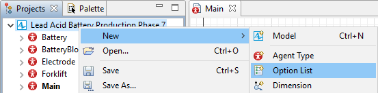
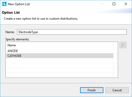
- In the New Option List dialog box specify the Name: ElectrodeType.
-
In the Specify elements table provide the names of the attributes: ANODE and CATHODE.
- The option list will appear in the project tree grouped in the
 Option Lists branch.
Add the parameter to the PlatesBatch agent
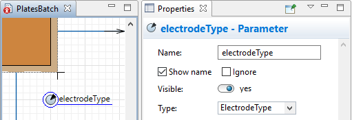
- Drag the
Parameter element from the
 Agent palette to the
PlatesBatch graphical diagram.
Agent palette to the
PlatesBatch graphical diagram. - Call it electrodeType.
-
In the Properties view of the parameter specify its Type: ElectrodeType.
The next step is changing the color properties of the batch animation figure.
Define the dynamic change of the color
-
Select the rectangle in the
PlatesBatch graphical diagram.
-
Switch the Fill color field to the dynamic value editor and type the following code: electrodeType == ANODE ? peru : silver.
We use this code to check the value of the electrodeType parameter and assign the color to the rectangle depending on the result. If the value is ANODE, the color is peru. Otherwise, the color is silver.
Now, let’s help our custom block differentiate between the two electrode types.
Define the electrode type for the prepareElectrode agent
- Add a parameter to the
PrepareElectrode agent.
- Name it electrodeType.
- In the parameter’s properties specify its Type: ElectrodeType and Label: Electrode type.
- In the properties of the batch block switch the New batch field to the dynamic value editor and specify the following: new PlatesBatch( electrodeType ).
- Go to the
Main graphical diagram. In the properties of the prepareAnode block specify the Electrode type: ANODE.
- In the properties of the prepareCathode block specify the Electrode type: CATHODE.
-
Run the model. Now the custom block passes the type of the electrode to the batches and the color of the batches changes accordingly.
-
How can we improve this article?
-