

Intersection is a graphical space markup element that is used to connect two or more roads. Using roads, intersections, and other space markup elements you draw road networks for Road Traffic Library models.
Intersection controls traffic directions with the help of lane connectors that indicate routes for cars on each road lane as vehicles cross the intersection.
To learn how to make traffic on the intersection controlled by a traffic light, see Controlled intersection.
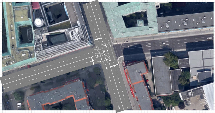
Let us demonstrate how to draw an intersection by the example of Wilhelmstrasse and Behrenstrasse intersection in Berlin, close to the Brandenburg Gate:
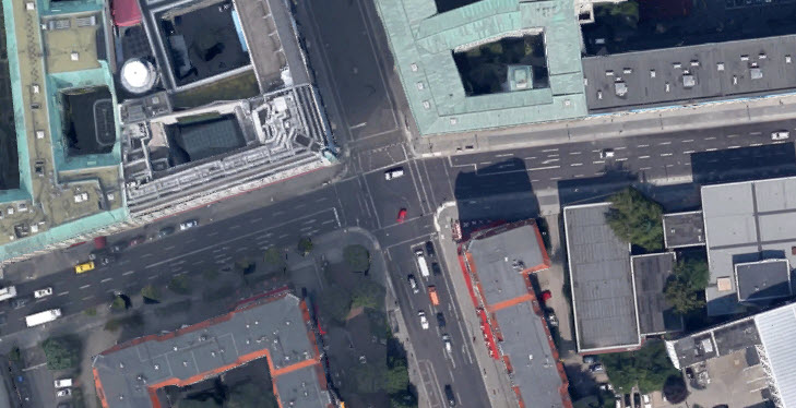
The scenario is typical for all kinds of intersections. Steps 1-3 demonstrate how to draw a T-shaped intersection, then we continue and end up with a four-way intersection.
To draw an intersection
- First, draw Wilhelmstrasse. You draw a linear road by double-clicking
 Road in the
  Road Traffic Library palette, then adding
the starting point of the road with a mouse click, and finally placing the final point of the road with a double-click.
Road Traffic Library palette, then adding
the starting point of the road with a mouse click, and finally placing the final point of the road with a double-click.
Both roads are two way, so it does not matter in what direction you will draw this road. To learn how to draw a road in more details, complete the short tutorial described in Road.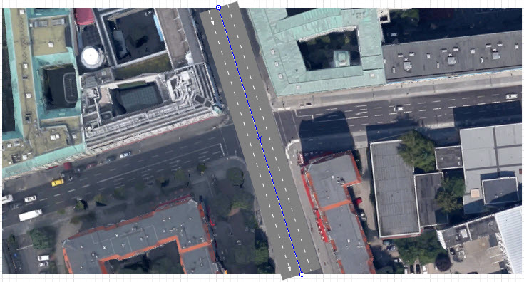
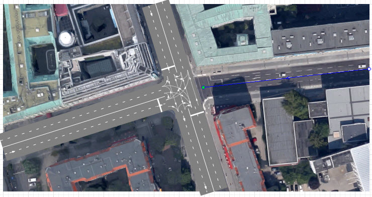
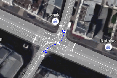
- Now let’s draw Behrenstrasse leading to the intersection from the left. Start drawing the road by clicking its median strip on the left border of the map image. The next step is to put the end point of the road that we are currently drawing. When moving the mouse over the certain points of Wilhelmstrasse, you will see cyan points indicating the possible connection points. To properly connect roads and get a T-shaped intersection, click the median of Wilhelmstrasse (see the figure below).
- The three-way intersection will be drawn. Every road connected to the intersection acquires a stop line on the lane with traffic moving towards the intersection. It is a regular AnyLogic stop line, that you can edit. You will also see a number of lane connectors drawn on the intersection. They define the allowed traffic directions on the intersection. By default they are typical for an intersection, so there is no need to edit them in our case.
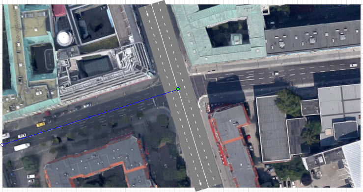
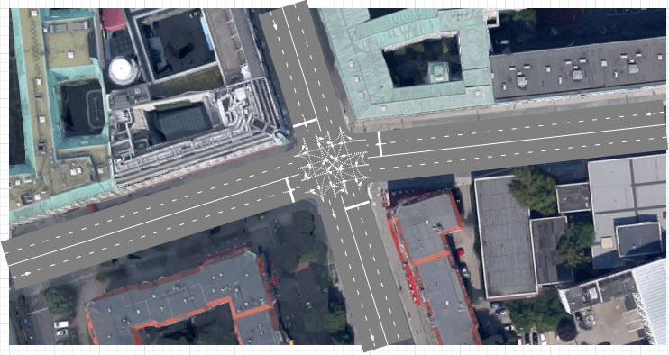
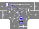
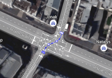
- Now draw Behrenstrasse leading to the intersection from the right. This time you should put the road end point close enough to Wilhelmstrasse so that you could see the cyan point, as shown in the figure below.
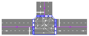
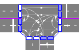
- A four-way intersection will be drawn. Please check that it has correct lane connectors and stop lines as shown in the figure below. If they form a different picture, try to redo some of the previous steps.
- General
-
Name — The name of the intersection. The name is used to identify and access the intersection in code and properties.
Ignore — If selected, the intersection is excluded from the model.
Visible on upper agent — If selected, the intersection is also visible on the upper agent where this agent lives.
Lock — If selected, the intersection shape is locked. Locked shapes do not react to mouse clicks — it is impossible to select them in the graphical editor until you unlock them. It is frequently needed when you want to prevent editing this shape while drawing other shapes over it.
Visible — Here you specify whether the shape is visible on animation at model runtime, or not. Using the control, choose yes or no.
- Advanced
-
Show in — Here you can choose whether you want the shape to be shown both in 2D and 3D animation, or in 2D only, or in 3D only.
Show name — If selected, the intersection’s name is displayed on the graphical diagram.
Lane connectors define the allowed traffic directions on an intersection. To enable car movement from one lane to the specific lane of other road, you should enable the lane connector linking the corresponding lane ends together.
By default AnyLogic enables the connectors that are typical for the intersection of the current topology.
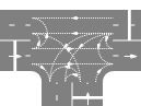
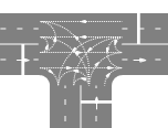
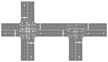 Default lane connectors for four-way intersection and T-shaped intersection
Cars strictly follow lane connectors on their way through the intersection.
If you need to customize traffic directions on the intersection, you may disable any existing connectors, draw more connectors, and alter connector shapes.
To disable existing lane connector
- Click the intersection to select it. The selected intersection will highlight the lane handles, one for each lane.
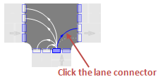
- Click the lane connector to select it.
- Press Delete. The lane connector will be removed and the movement in this direction will be prohibited.
To draw more lane connector(s)
Let us demonstrate how to enable traffic direction from the lower road to the right road.
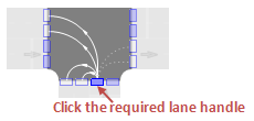
- Click the intersection to select it. The selected intersection will highlight the lane handles, one for each lane.
- Click the lane handle referring to the lane you want to add connector(s) to. You will enter the lane connector editing mode, containing all enabled (drawn as solid white lines) and disabled (marked in grey) lane connectors leading to or from
the current lane, depending on its traffic direction.
- Click the disabled lane connector to enable it. Once it turns white, it becomes active. In this way you may enable/disable traffic direction(s) from the selected lane.
- Click an empty spot of the graphical editor to quit the lane connectors editing mode. You will see the changes that you’ve just made.
If default connectors created by AnyLogic are similar to the ones you need, you can just slightly adjust them. However, if they differ drastically, it may be simpler to draw all the required lane connectors from scratch. In this case you should start with deleting all the existing lane connectors.
To delete all lane connectors
- Right-click the intersection and choose Clear Lane Connectors from the context menu. Make sure not to right-click any lane connector of this intersection, this will invoke lane connector’s context menu with other commands.
To reset lane connectors to default
- Right-click the intersection and choose Reset Lane Connectors to Default from the context menu. Make sure not to right-click any lane connector of this intersection as it will invoke lane connector’s context menu with other commands.
To alter the lane connector shape
- Click the intersection to select it.
- Click the lane connector you want to edit.
- You may see a rectangle node on the connector’s shape if it is long enough. It is connector’s salient point. The smaller connectors do not have salient points by default. If you need a connector of a complex shape, add one more salient point. To add a salient point, double-click in the certain spot of the lane connector’s shape.
- Move salient point(s) by dragging. You will see that the connector’s shape is changing.
- When done, release the mouse button. The cars using this lane connector will follow its new shape as they cross the intersection.
- Click the empty spot of the graphical editor to deselect the lane connector.
To make a lane connector linear / curved
- Click the intersection to select it.
- Right-click the required lane connector and choose Make Segment Linear/Arc-based from the context menu.
- On hovering your mouse over a segment, you will see the preview of the shape the segment will acquire if you click on it. Now click on the segment you want to change.
- You can change shapes of other segments if needed. When done, click on an empty spot on the graphical diagram to switch off this editing mode.
- Cars
-
Function Description int nCars() Returns the number of cars located on this intersection. List<Agent> getCars() Returns unordered list of cars located on this intersection. - Lane connector statistics
-
Function Description int traffic() Returns the number of cars that have passed through this lane connector during 1 hour of model time. To obtain this result, we count the cars that have passed through this intersection during the last 5 minutes of model time and multiply this number by 12. int countCars() Returns the total number of cars that have passed through this lane connector since the start of the model run. void resetStats() Resets the counters for countCars() and traffic() functions of the lane connector. - Intersection statistics
-
Function Description int traffic(Road from, Road to) Returns the number of cars that have passed between the specified lanes during 1 hour of model time. This result is the sum of traffic() for each lane connector between the specified lanes.
from - a lane connected to the intersection
to - a lane connected to the intersectionint countCars(Road from, Road to) Returns the number of cars that have passed between the specified lanes since the start of the model run. The result is the sum of countCars() for each lane connector between the specified lanes.
from - a lane connected to the intersection
to - a lane connected to the intersectionvoid resetStats() Resets the counters for countCars() and traffic() functions of the intersection. - Visibility
-
Function Description void setVisible(boolean v) Sets the visibility of the intersection.
v — visibility of the intersection: if true — the intersection is visible, if false — not visible.boolean isVisible() Returns the visibility of the intersection. If it returns true, the intersection is visible, if false — not void showLaneConnectors(boolean showLaneConnectors) Returns the visibility of lane connectors of the intersection.
showLaneConnectors — visibility of lane connectors: if true — the connectors are visible, if false — not visible. - Advanced
-
Function Description RoadNetwork getRoadNetwork() Returns the road network this intersection belongs to. List<RoadLanesConnector> getLanesConnectors() Returns the list of lane connectors inside this intersection. - Level
-
Function Description Level getLevel() Returns the level, where this intersection is located. - Removal
-
Function Description void remove() Removes the intersection from the presentation. If the intersection is not a part of presentation, the function does nothing. Note, that removal from the presentation does not necessarily mean removing from the model logic, since logical networks and routes may have been created before the removal and survive it.
-
How can we improve this article?
-