

In this part of our tutorial, we’ll simulate the CNC machines that process raw materials. We’ll start by marking up the space and using point nodes to define the CNC machine locations.
- On the
 Space Markup palette, drag the
 Point Node element on to the job shop layout, and name it nodeCNC1.
 -
Copy this node to mark up the space for the second CNC machine.
AnyLogic will name the second node nodeCNC2.
We’ll need to create paths to connect both of these nodes to our network. Our model’s forklift trucks will need them to reach the CNC machines.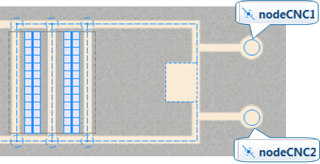
-
On the
Space Markup palette, click the
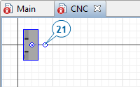
 Path element and draw paths as shown in the figure below. To connect a path to a point node, click the point node’s center.
Make sure the paths that you draw connect the nodeCNC1 and nodeCNC2 to the network. You can test a path’s connection by selecting it with a click. If the path is connected to the network, cyan highlights will appear around its end points.
Path element and draw paths as shown in the figure below. To connect a path to a point node, click the point node’s center.
Make sure the paths that you draw connect the nodeCNC1 and nodeCNC2 to the network. You can test a path’s connection by selecting it with a click. If the path is connected to the network, cyan highlights will appear around its end points.
A CNC machine is a resource unit, and we’ll add it to our model by creating a resource type and using the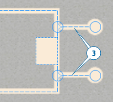
 ResourcePool block to define the resource pool.
- On the
 Process Modeling Library palette, click and drag the
ResourcePool block onto the
Process Modeling Library palette, click and drag the
ResourcePool block onto the
 Main diagram.
 -
In the
ResourcePool block’s
 Properties view, do the following:
- In the Name box, type cnc.
- In the Resource type list, click Static to reflect the fact this is a static resource.
With our resource pool complete, we’re ready to create a new resource type.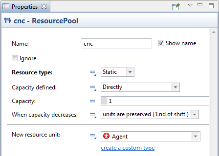
- Under the New resource unit list, click the create a custom type link.
-
In the New agent wizard, do the following:
- In the Agent type name box, type CNC.
- Click Next.
- On the next page of the wizard, expand the CNC Machines section, and select CNC Vertical Machining Center 2 State 1.
- Click Finish.
- Close the new CNC type’s diagram and return to the
Main diagram.
-
In the cnc
ResourcePool block’s
Properties view, do the following to place our model’s two CNC machines at the places defined by our point nodes, nodeCNC1 and nodeCNC2.
-
In the Capacity defined list, click By home location.
The By home location option sets the number of resources equal to the number of home location nodes that you set for this resource pool. -
Click the plus button
 and then add nodeCNC1 and nodeCNC2 into the Home location (nodes) list.
After you’ve added the nodes, the list should resemble the figure below.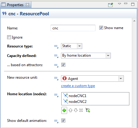
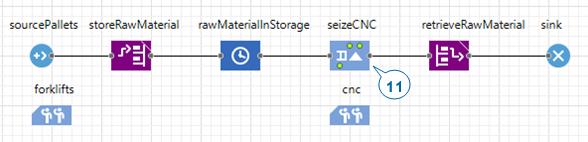
 Seize block that will seize a CNC machine. Later, a
 Delay block will simulate a CNC machine’s processing of raw materials and a
 Release block will release a CNC machine so it can process the next pallet’s raw material.
Remember that our model’s flowchart already has a retrieveRawMaterial block that simulates the moving resource (the forklift trucks) that delivers pallets to the CNC machine.
Release block will release a CNC machine so it can process the next pallet’s raw material.
Remember that our model’s flowchart already has a retrieveRawMaterial block that simulates the moving resource (the forklift trucks) that delivers pallets to the CNC machine. -
In the Capacity defined list, click By home location.
- In the flowchart that defines the pallets’ behavior, drag the retrieveRawMaterial and sink blocks to the right to make space for a new block.
-
On the
Process Modeling Library palette, drag the
Seize block, and insert it in the pallets’ flowchart after the rawMaterialInStorage block.
-
In the
Seize block’s
Properties view, do the following:
- In the Name box, type seizeCNC.
-
Under the Resource sets option, click the plus button , and then click cnc.
Completing this step ensures the Seize block will seize one resource from the cnc resource pool.
-
In the retrieveRawMaterial flowchart block’s
Properties view, do the following:
- In the Destination is list, click: Seized resource unit.
-
In the Resource list, click cnc.
This block will simulate how the pallets are transported to the seized CNC machine rather than the forklift trucks’ parking zone.
-
Do the following to simulate the CNC machine’s processing of raw materials:
-
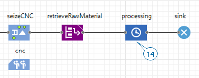
Add a
Delay block, place it immediately after retrieveRawMaterial, and name it processing.
-
Add a
-
In the
Delay block’s
Properties view, do the following:
- In the Delay time box, type 1 and select minutes from the list on the right.
-
Select the Maximum capacity check box to allow the machines to process several pallets.
Each agent that arrives to the Delay block must have one of our model’s two CNC machines.
- On the
Process Modeling Library palette, drag the
Release block on to the pallets’ flowchart and place it after the processing block.
-
Name this
Release block releaseCNC.
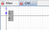
If you run the model, you’ll see that while the processes are simulated correctly, the 3D animation draws a pallet in the middle of the CNC machine shape. This occurs when the CNC machine and the pallet it is processing both use the same point node as the animation location. To resolve the problem, we’ll need to shift the CNC machine to the right and rotate it to face the pallet.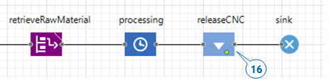
- In the Projects view, double-click the CNC agent type to open its diagram.
-
Move the animation to the right, and rotate the CNC machine shape by using the round handle or setting the figure’s Rotation property to 90 degrees.
We are ready to use two similar 3D animation shapes to animate the CNC machine: one shape will represent the idle machine and the other will represent the machine as it processes the raw materials. We’ll define dynamic values for each shape’s Visible property that will allow our model to use the CNC machine’s state to determine which shape the model will display at runtime.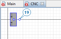
-
Do the following to change the CNC animation shape’s visibility setting:
- Select the CNC animation shape.
-
Hover your mouse over the static parameters icon that displays
 next to the Visible label and click Dynamic value.
The icon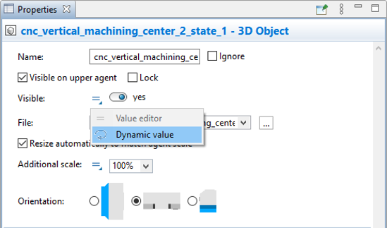 changes to a dynamic properties icon
  and a box where you can define the value's dynamic expression displays. You can use the box to enter Java expression that returns a true or false value.
-
In the box, type isBusy().
This standard function for an AnyLogic resource returns true when the resource is busy. In our case, the function will make the 3D animation shape display when the CNC machine is processing raw materials.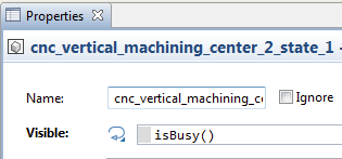
Dynamic properties
When you define an expression for a property’s dynamic value, our model will re-evaluate the expression on every animation frame during runtime, and then use the resulting value as the property's current value. Providing dynamic values for a shape’s position, height, width, or color allows AnyLogic users to animate their models.
If you do not enter a dynamic value, the property retains the default static value throughout the simulation.
-
Flowchart blocks can have:
- Static parameters that retain the same value throughout the simulation unless a set_parameterName(new value) function changes it.
- Dynamic properties whose value is re-evaluated each time a new agent enters the block.
 Code parameters that allow you to define actions that will be executed at a key moment in the flowchart block such as the On enter action or On exit action. In most cases, you’ll find code parameters in a flowchart block’s
Properties view, in the Actions section.
Code parameters that allow you to define actions that will be executed at a key moment in the flowchart block such as the On enter action or On exit action. In most cases, you’ll find code parameters in a flowchart block’s
Properties view, in the Actions section.
- The small triangle at the parameter icon shows that you can click the icon and switch between static value editor and the field where you can enter the value’s dynamically re-evaluated expression.
-
Flowchart blocks can have:
-
Do the following to add one more animation shape that will be visible only when the CNC machine is not processing raw materials.
- Open the
 3D Objects palette that contains ready-to-use 3D objects of AnyLogic.
 - Expand the CNC Machines area and drag the CNC Vertical Machining Center 2 State 2 shape on to the CNC diagram.
- In the displayed Auto scale 3D object dialog box click the Yes button.
- Rotate the shape and place it directly on top of the first animation figure.
-
In the Visible box, switch to the dynamic value editor, and type isIdle() as the dynamic expression for the shape’s Visible property.
- Open the
-
Expand the People section on the
3D Objects palette and drag the Worker shape on to the CNC diagram.
-
Finally, make the network invisible at runtime. Open the Main diagram. Select the network and set its Visible property to no.
Remember that your first click will select the network element and your second click will select the network. -
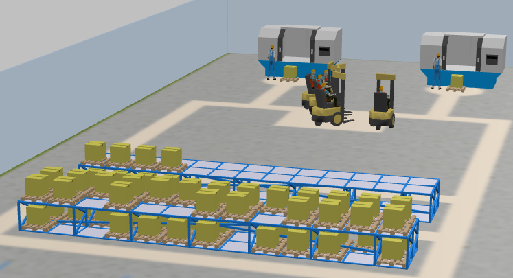
Run the model and observe the process.
You’ll see how forklift trucks transport pallets to CNC machines for processing. You should also see animated CNC machines, changing 3D shapes depending on their state.
We have finished our simple model that simulates the manufacturing and shipping process in a small job shop. You now have a basic knowledge of AnyLogic resources and how to work with them. You also know how to use a flowchart constructed from the
Process Modeling Library blocks to define process logic. Your next step might be to model how the pallets with the finished parts are moved to another storage area at the shipping dock where they will stay until they are shipped. You’ve already used the blocks that you’ll need to model this part of the process, so you may want to try adding this logic on your own.
-
How can we improve this article?
-