

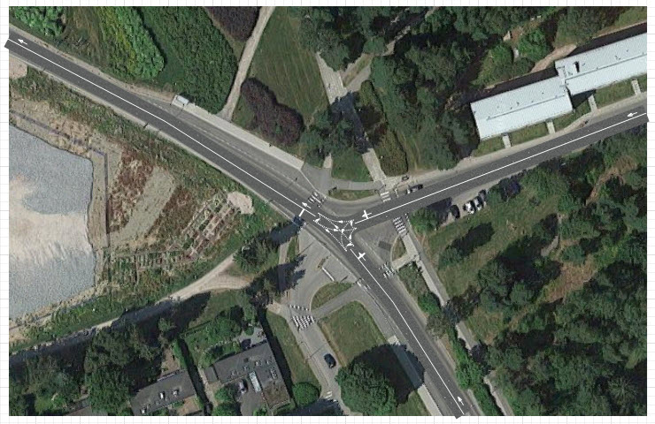
The cars in our model are currently moving from South to North-West along the Tapiolavagen road in one direction only.
This phase is devoted to creating an intersection by drawing Menninkaisentie road that will connect to Tapiolavagen road from the East. We will add new blocks to the flowchart afterwards to model car movement on both roads in all directions.
Draw an intersection
Intersections in AnyLogic are drawn automatically on every road connection. Draw Menninkaisentie road connecting to Tapiolavagen road from the East.
- Traditionally we will start with double-clicking the
 Road element in the Space Markup section of
 Road Traffic Library palette.
 - Start drawing the road by clicking the median strip of the Menninkaisentie road at the right border line of the map image.
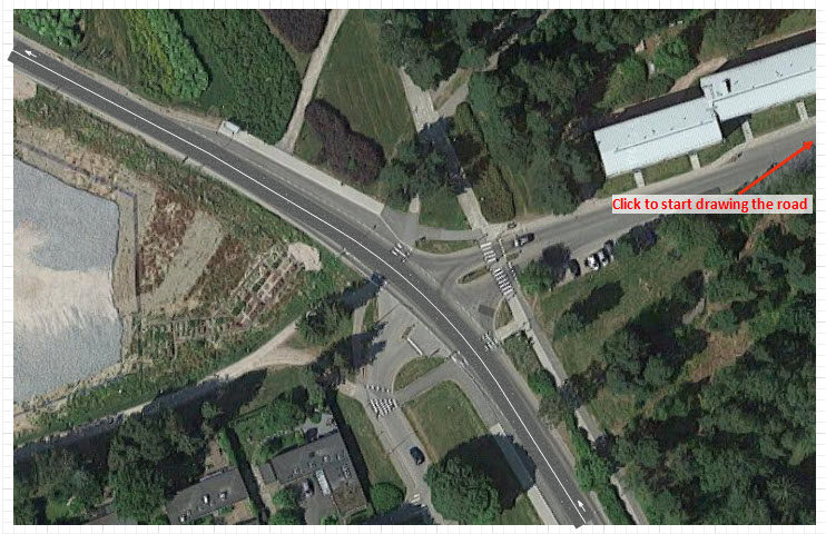
- Add the end point of the road. To properly connect roads and get a T-shaped intersection, hover your mouse over the median of Tapiolavagen road and double-click it when you see a cyan point (see the figure below).
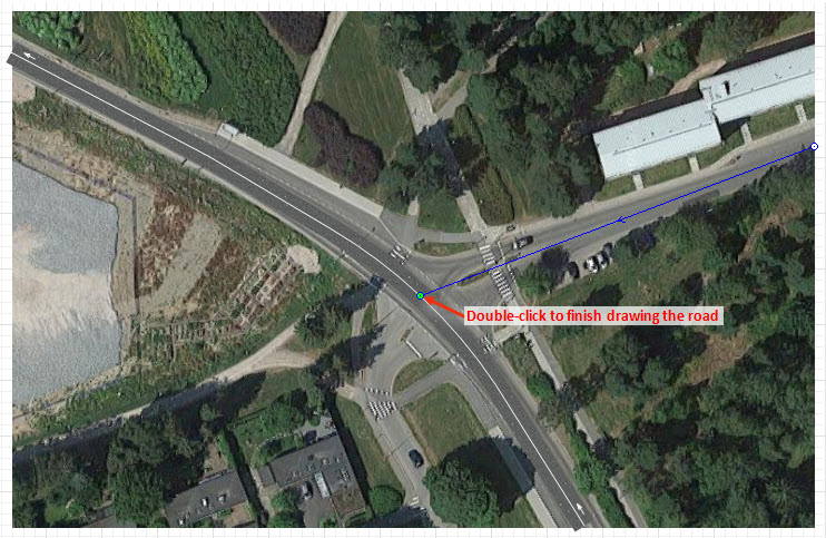
- T-shaped intersection will be created.
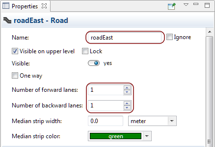
- The drawn road contains two lanes in both directions while the actual Menninkaisentie road consists of one forward lane and one backward lane. Hence, we need to customize the road attributes. Click the road to open the Properties view. Change both Number of forward lanes and Number of backward lanes parameters to 1. The number of lanes will automatically decrease.
- To make it easier later to refer to this road from the flowchart blocks, we should change the road’s Name to roadEast.
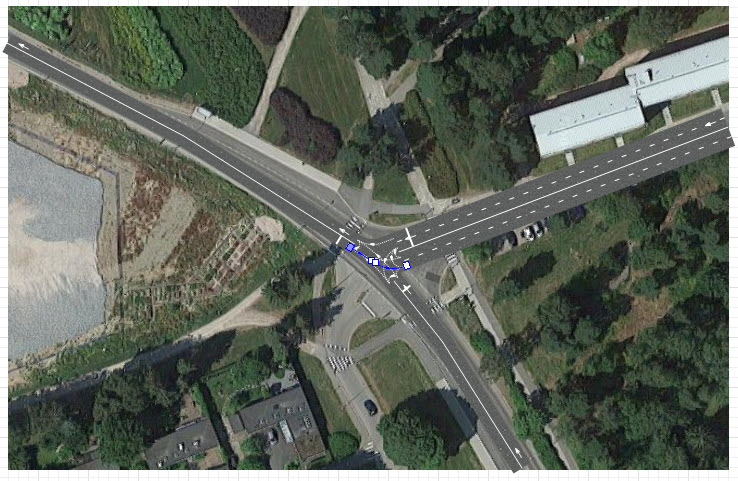
- Once you make the previously described changes the road network should look similar to the one on the figure below.
If you run the model now, you will notice that the cars move to the intersection only and not to the end of the Tapiolavagen road. It is accounted for by the fact that connecting a new road to the existing one creates a new intersection, the AnyLogic markup element dividing the existing road into two separate roads.
Our flowchart contains CarSource block, which generates cars entering forward lane of the
road and
 CarMoveTo block, which models car movement to the end of the same road. The road currently ends at the intersection due to the fact that the road at the other side of the intersection is a completely new road now, named
road2.
CarMoveTo block, which models car movement to the end of the same road. The road currently ends at the intersection due to the fact that the road at the other side of the intersection is a completely new road now, named
road2.
Let us rename the two roads to make it easier later to refer to them from the flowchart blocks.
Rename the roads
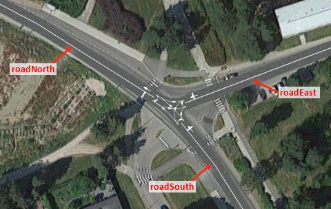
- Select and rename the roads to: roadNorth, roadSouth, and roadEast correspondingly (see the figure below).
Since carSource and carMoveTo flowchart blocks still refer to old road names, we need to specify the correct name in their Properties.
Adjust the properties of the flowchart blocks
- Select the carSource block. Change its Name to carSourceS (to accentuate that the block generates cars, which appear from South direction).
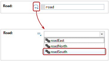
- In the Road parameter of this block you will see the old name of the road. To change it to the new one, click the
 button to the left of the Road field to switch from the dynamic value insertion mode to the static element selection mode. Then choose
roadSouth from the drop-down list (see the figure below).
button to the left of the Road field to switch from the dynamic value insertion mode to the static element selection mode. Then choose
roadSouth from the drop-down list (see the figure below).
- Make the same changes in the carMoveTo block’s properties. Name it carMoveToN (it will model car movement to the end of the road going North) and choose
roadNorth from the Road drop-down list.
On running the model now, you will see that the cars are moving from South to North along the Tapiolavagen road again.
However, we did not create the intersection to please ourselves with the car movement along one road only. Our next step is to add flowchart blocks to make cars move on all roads in every possible direction.
Add new blocks to the flowchart
- First, we need to move the existing flowchart down and place it below the blue rectangular frame of the model window, since our flowchart will grow bigger and will not fit in the area below the layout that is shown at model runtime.
- Now we will add blocks that will model car movement from North to South on the same road (on the backward lane of the Tapiolavagen road). Add another
CarMoveTo block. Connect them to the existing blocks in the following way:
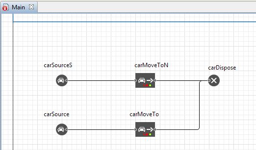
As you can on see on the screenshot, the blocks' connectors have complex shape. To connect the ports of two blocks to a connector of a custom shape, start drawing by double-clicking the first port and then (if needed) add connector’s turning points by clicking in the corresponding spots of the graphical editor. Finish drawing with a double-click on the second port.
Adjust the properties of the added flowchart blocks
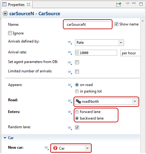
- Rename carSource block to carSourceN (this block generates cars appearing from the North direction).
- In the Road parameter choose
roadNorth. It is the road the cars will appear on.
- Choose backward lane in the Enters parameter since we need the cars to appear at the beginning of the backward lane of this road (at its North end).
- Open the Car properties section and choose
 Car in the New car parameter. From now on the carSourceN block will be generating cars of the specified
Car type. These cars will have the shape of the previously defined green car instead of the colored parallelepipeds offered by default.
Car in the New car parameter. From now on the carSourceN block will be generating cars of the specified
Car type. These cars will have the shape of the previously defined green car instead of the colored parallelepipeds offered by default.
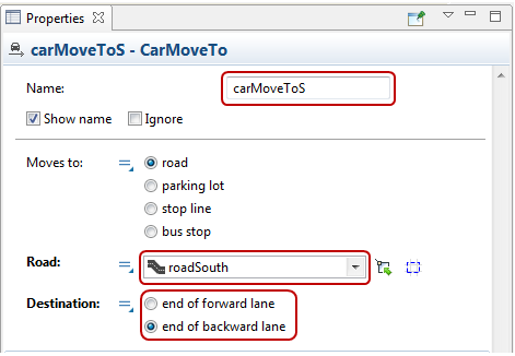
- Make the same changes in the carMoveTo block. Name it carMoveToS (it will model car movement in the South direction), Choose
roadSouth in the Road parameter and set end of backward lane in the Destination parameter.
If you run the model now, you will see cars moving along the Tapiolavagen road in both directions.
The following step will be devoted to modeling car movement from the East, along the Menninkaisentie road. Certain quantity of the cars (half of them approximately) will be heading South after the intersection while the remaining part of the cars will be heading North.
Add new blocks to the flowchart
- Add another CarSource block (it will generate cars at the beginning of the Menninkaisentie road).
- Name it carSourceE and choose
roadEast in the Road parameter. Open the Car properties section and choose
Car in the New car parameter.
- Switch to the
 Process Modeling Library palette and add
 SelectOutput block to the flowchart, placing it close to the just created carSourceE block.
 - Name it selectNS.
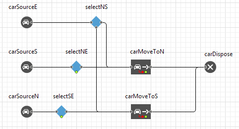
- Connect the two output ports of the
SelectOutput block to the input ports of the carMoveToN and carMoveToS blocks. The flowchart should look like this:
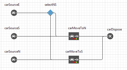
The
SelectOutput redirects the incoming agents (cars in our case) to one of its output ports according to the predefined probabilities or depending on the execution of the specified condition. By default the block is operating according to the specified probability, directing approximately 50% of agents to the upper output port, which is fine in our case and we will keep the default settings of the block.
Road traffic model flowcharts are most frequently constructed out of the Road Traffic Library blocks
 CarSource,
CarMoveTo, and
CarSource,
CarMoveTo, and
 CarDispose, as well as with the help of the Process Modeling Library blocks
![]() SelectOutput or
SelectOutput or
![]() SelectOutput5 (to route cars in various directions) and Delay (block is used to model the time cars spend in the parking lots or at the bus stops). We will cover these cases further in this tutorial.
SelectOutput5 (to route cars in various directions) and Delay (block is used to model the time cars spend in the parking lots or at the bus stops). We will cover these cases further in this tutorial.
If you run the model, you will see that cars are moving along the Tapiolavagen road in both directions and they are also coming from the East moving along the Menninkaisentie road, heading either South or North afterwards. The only thing that is left to do is to model the turn from Tapiolavagen to Menninkaisentie.
Let us add a few more blocks to the flowchart to model this last car movement scenario.
Modify the flowchart
- Add
SelectOutput block from the Process Modeling Library. Place it between the carSourceS and carMoveToN blocks (in such a way that it could be connected to both of the blocks as shown on the screenshot below). We need this block to distribute the traffic flow between the East and the North directions. Name it selectNE.
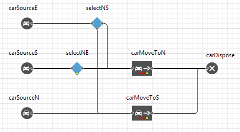
- Open the block’s properties to set the routing for cars. We shall assume that the majority of cars moving along the main road (approximately 70%) will continue to move along the same road. In this case we need to adjust the quantity of cars which will be redirected to the first output port of the
SelectOutput block. Type 0.7 in the block’s Probability parameter. As a result the average quantity of 70% will be directed to the upper port while 30% will be directed to the lower port (we will connect the lower port to the corresponding block later).
- Add another
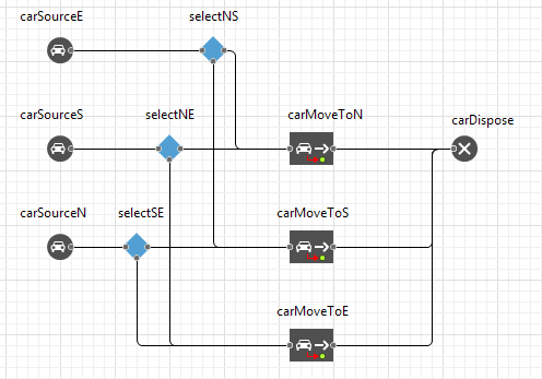
SelectOutput block and name it selectSE. Place it between the carSourceN and carMoveToS blocks (see screenshot below). We need this block to define the movement direction for cars coming from the North. Similar to the previous block’s properties adjustment set the fraction of cars, which will continue moving along the same road, to 70% by typing 0.7 in the Probability parameter.
- Switch to the
Road Traffic Library palette and add
CarMoveTo block. Name it carMoveToE (it will model car movement on the Menninkaisentie road in the Eastern direction). Connect the incoming port to the lower ports of the both (!) selectNE and selectSE blocks. Then connect the output port to the carDispose block as shown on the figure below.
- Click the block to open its
 Properties view. Choose
roadEast in the Road parameter and set Destination parameter to end of backward lane.
Properties view. Choose
roadEast in the Road parameter and set Destination parameter to end of backward lane.
We have finally completed the flowchart logic defining car movement on the intersection. Run the model and watch cars move along the roads.
Demo model: Road Traffic Tutorial — Phase 3 Open the model page in AnyLogic Cloud. There you can run the model or download it (by clicking Model source files). Demo model: Road Traffic Tutorial — Phase 3Open the model in your AnyLogic desktop installation.-
How can we improve this article?
-