

Paths and nodes are space markup elements that define the locations of agents in the space:
- Path graphically defines a movement path for agents.
- Node defines a location where agents can reside.
Nodes can be connected to paths. Together they form a network. AnyLogic also automatically creates a separate network for each individual path element that is not connected to a node.
In the network, a node defines a place where agents can stay, while paths connecting nodes define the routes that agents can take when moving from one node to another. Movement is always performed along the shortest path between the origin and the destination nodes. Agents and resource units can have individual speeds, and these speeds may change dynamically. For example, you can set a different speed for the loaded and the unloaded forklift truck. Segments are assumed to have unlimited capacity, so agents moving along a segment will not interfere.
You can select a path as Agent location in the properties of the following Process Modeling Library blocks: Delay, Queue, Match, Combine, Seize, Service, BatchConveyor, RackStore.
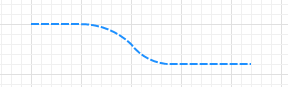
A path can contain any number of linear and curved segments.
To draw a path
-
Double-click the
 Path element in the
  Space Markup palette.
The icon of the element should change to . This means that the drawing mode is activated, and you can now draw the path point by point in the graphical editor.
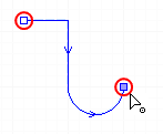
- Click in the graphical editor to draw the first point of the path. Click again to add more points.
-
To draw a curved segment, click and hold the left mouse button at the next turn point of the path and move the mouse until you get the segment of the desired shape. Release the mouse button when you have finished adjusting the shape of the path segment.
- Double-click to set the final point of the path.
You can continue drawing the path after you have finished it with the double-click and edit the path by making the segments linear or curved.
- General
-
Name — The name of the path. The name is used to identify and access the path from code and flowchart block properties.
Ignore — If selected, the path is excluded from the model.
Visible on upper agent — If selected, the path is also visible on the upper-level agent that hosts the agent containing this path.
Lock — If selected, the path is locked. Locked elements do not respond to mouse clicks, and they cannot be selected in the graphical editor until you unlock them. This is often needed when you want to prevent the element from being edited while other elements are placed over it.
Visible — Specifies whether the shape is visible on animation at model runtime, or not. Using the control, choose yes or no.
Bidirectional — Allows movement on the path in both directions.
Speed limit for transporters — If selected, limits the speed of transporters on this path to the specified value.
Limit number of transporters — If selected, limits the total number of transporters on this path.
- Appearance
-
Type — The type of the path. Choose from Dashed line, Line, Road, Railroad, or Conveyor.
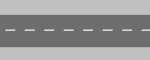
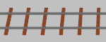
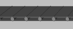
Road Railroad Conveyor By setting Type to Road, Railroad, or Conveyor, you only change the visual appearance of the path. It does not add any specifics to the path logic. Typically, you only use such paths in the models with a high abstraction level.
For road traffic simulation, use the Road Traffic Library and road traffic markup shapes (road, intersection, and so on).
For low-level railway simulation (considering each individual track of the simulated rail yard), use the Rail Library and rail markup shapes.
For bulk transportation simulation, use the Fluid Library and the Bulk conveyor belt markup shape.Line color — The path color if the type is Dashed line or Line.
Line width — The width of the path if the type is Dashed line or Line.
Width — The width of the path when its type is set to Road, Railroad, or Conveyor.
- Position
-
X — The X-coordinate of the path’s start point.
Y — The Y-coordinate of the path’s start point.
Z — [Enabled if Show in: 2D and 3D or 3D only options are selected] The Z-coordinate of the path’s start point.
- Points
-
The table located in the Points property section allows you to view and set the coordinates of the path’s turning points.
The coordinates are relative, not absolute. The first point always has coordinates (0, 0, 0) that cannot be changed.
Other rows of the table define relative coordinates of the successive points. The coordinates of each point are actually offsets of the corresponding point from the start point along the X, Y (and optionally Z) axes correspondingly.
- Advanced
-
Show in — Here you can choose whether you want the shape to be shown both in 2D and 3D animation, or in 2D only, or in 3D only.
Show name — If selected, the path’s name is displayed on the graphical diagram.
You can dynamically modify the path properties at model runtime using the following API.
- Length
-
Function Description double length() Returns the length of the path (in pixels) calculated in 3D space. double length(LengthUnits units) Returns the length of the path calculated in 3D space.
units — one of the chosen length units. - Points
-
Function Description Point getStartPoint() Returns the Point object with coordinates of the path’s starting point. Point getStartPoint(Point out) Returns the Point object with coordinates of the path’s starting point.
out — the output point to write result to.Point getEndPoint() Returns the Point object with coordinates of the path’s ending point. Point getEndPoint(Point out) Returns the Point object with coordinates of the path’s ending point.
out — the output point to write result to.Position getStartPosition() Returns the Position object with coordinates and orientation of the path’s starting point. Position getStartPosition(Position out) Returns the Position object with coordinates and orientation of the path’s starting point.
out — the output position to write result to.Position getEndPosition() Returns the Position object with coordinates and orientation of the path’s ending point. Position getEndPosition(Position out) Returns the Position object with coordinates and orientation of the path’s ending point.
out — the output position to write result to.boolean contains(double px, double py) Returns true if the path contains the point with the given coordinates; returns false otherwise.
px — the X-coordinate of the point.
py — the Y-coordinate of the point.boolean contains(double px, double py, double distance) Returns true if the path contains the point with the given coordinates using the given distance tolerance; returns false otherwise.
px — the X-coordinate of the point.
py — the Y-coordinate of the point.
distance — the distance tolerance to determine whether the given point lies within the markup element line proximity.boolean containsSq(double px, double py, double squareDistance) Returns true if the path contains the point with the given coordinates using the given square distance tolerance; returns false otherwise.
Returns true if the shape contains the point with the given coordinates. px — the X-coordinate of the point.
py — the Y-coordinate of the point.
squareDistance — the square of distance tolerance to determine whether the given point lies within the markup element line proximity.double getNearestPoint(double x, double y, Point out) Calculates the point in this path nearest to the given (x, y) point and writes the result to the output Point object. Returns the square of the distance to the point. All calculations are performed in the horizontal XY-projection (i.e. z-coordinates are treated as zeros).
x — the x coordinate of the point.
y — the y coordinate of the point.
out — the output point to write result to.double getNearestPoint(double x, double y, double z, Point out) Calculates the point in this path nearest to the given (x, y, z) point and writes the result to the output Point object. Returns the square of the distance to the point.
x — the x coordinate of the point.
y — the y coordinate of the point.
z — the z coordinate of the point.
out — the output point to write result to.Position getPositionAtOffset(double offset, Position out) Returns the Position object with coordinates and orientation of the point that is located at the given offset distance (in pixels) from the path’s starting point.
offset — offset, non-negative value, should be less or equal to the full length.
out — output object to write to, may be null.Position getPositionAtOffset(double offset, LengthUnits units, Position out) Returns the Position object with coordinates and orientation of the point that is located at the given offset distance from the path’s starting point.
offset — offset, non-negative value, should be less or equal to the full length.
units — one of the chosen length units.
out — output object to write to, may be null. - Network ports
-
Function Description NetworkPort createPort(PathEndType endType) Creates a network port at the starting or the ending point of the path, depending on the argument value.
endType — Specifies whether the port should be created at the path’s starting or ending point. Possible values: PathEndType.BEGIN, PathEndType.END.NetworkPort createPort(PathEndType endType, NetworkPort pairedPort) Creates a network port at the starting or the ending point of the path, depending on the argument value. The resulting port will be paired with the specified port in another network.
endType — Specifies whether the port should be created at the path’s starting or ending point. Possible values: PathEndType.BEGIN, PathEndType.END.
pairedPort — A network port that belongs to another network.When a network port is created programmatically, it can only be paired with ports created the same way. To create a connection between ports you have created in the graphical editor, use their properties.
- Segments
-
Function Description int getSegmentCount() Returns the number of the path’s segments. MarkupSegment getSegment(int index) Returns the segment by the provided index.
index — the segment index, starting from zero up until the number of segments -1. - Nodes
-
Function Description Node getSource() Returns the path’s source node. Node getTarget() Returns the path’s target node. - Visibility
-
Function Description boolean isVisible() Returns true if the path is visible; returns false otherwise. void setVisible(boolean v) Sets the visibility of the path.
v — visibility. If v is true — the path is set to be visible, if it is false — not visible. - Color and texture
-
Function Description Color getLineColor() Returns the color of the path, or null if the path has no color or uses a texture (in this case use getLineTexture() to get the path’s texture). Texture getLineTexture() Returns the texture of the path or null if the path has no texture but uses a color (in this case use getColor() to get the path’s color). void setLineColor(Color color) Sets the color of the path.
color — the new color.void setLineColor(Paint color) Sets the color (or texture) of the path.
color — the new texture. - Level
-
Function Description Level getLevel() Returns the level, where this path is located. - Appearance
-
Function Description double getLineWidth() Returns the width of the path outline (in pixels). double getLineWidth(LengthUnits units) Returns the width of the path outline.
units — one of the chosen length units.void setLineWidth(double width) Sets the width of the path outline; 0 means the thinnest possible outline.
width — the new width of the path outline (in pixels).void setLineWidth(double width, LengthUnits units) Sets the width of the path outline; 0 means the thinnest possible outline.
width — the new width of the wall path (in pixels).
units — one of the chosen length units. - Removal
-
Function Description void remove() Removes the path from the presentation. If the path is not a part of presentation, the function does nothing. Removal from the presentation does not necessarily mean removing from the model logic, since logical networks and routes may have been created before the removal and survive it.
Every path has a direction — the first point you draw is treated as the starting point of the path.
When a path animates any block of the Process Modeling Library (for example, Queue), where you place the starting point of the path is important:
- The Conveyor block transports parts from the start point to the end point of a path.
- The Queue block places agents in its queue from the end to the start point of a path (the end point corresponds to the head of the queue).
To find out the direction of a path, click it in the graphical diagram. The direction of the path is indicated by the arrow displayed on the path shape. The arrow is always displayed on the shapes of unidirectional paths.
To change the direction of the path
- Right-click the path in the graphical diagram and select Change Direction from the context menu. You will see that the arrows have changed direction.
To add a segment to the path
-
Right-click the path you have drawn and select Append line from the context menu. You can append a line to any end point of the path by clicking this point.
- You are now in the drawing mode. You can add as many new segments as you need, both linear and curved.
- Put the final point of the path with the double-click.
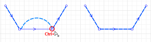
To make a curved segment linear
- Click a path in the graphical editor to select it.
- Press Ctrl button on your keyboard and hold it. At the same time drag end point of the curved segment.
-
Release the buttons when the segment has the required shape.
To make a linear segment curved
-
Right-click the path and select Edit Using Guiding Lines from the context menu. The guiding lines will appear for editing points. Left-click an editing line point and drag it around without releasing the left mouse button.
- Right-click the path and clear Edit Using Guiding Lines from the context menu to switch off this editing mode.
Several paths can be connected together, with or without the use of nodes. You can disconnect the paths too.
To connect two or more paths into one path
-
When you connect two paths at their end points, they become one path. In the example below, the option Append Line was used to connect path to path1.
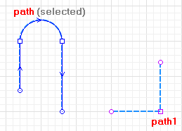
-
The connecting point where the two paths merge is highlighted with the cyan color. Two shapes have now become one element,
path. The former segments of path1 have inherited the name and the
direction.
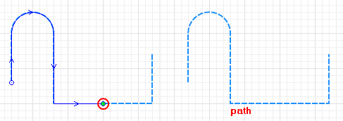
- As long as you connect the paths by their edge segments, they will merge into one path.
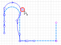
To connect two or more paths with a point node
-
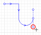
You can connect paths using a point node if you draw a segment that connects anywhere to the path and not to its end point. In the example below, the element path was connected to path1 in the middle. Multiple paths can be connected with each other this way.
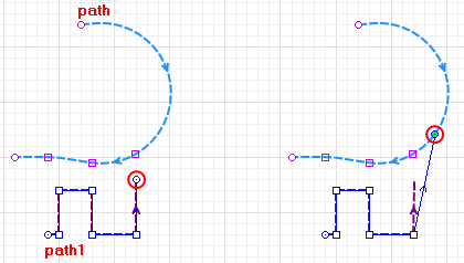
-
The point node will appear in the place of connection. It is highlighted in the cyan color. Now you have created network with several paths in it. In the example below, the point node breaks the path into parts, path and
path2 while path1 does not merge with path, but remains a separate path.
You can connect in one point node as many paths as you need.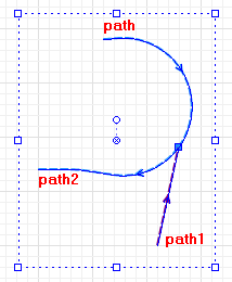
- The first click selects all elements of this network, make one more click to select the point node. Right-click the point node in the graphical editor and select Create node from the context menu to create the Point node element in the point of connection.
You can split the paths that are connected at the point node or split one whole path into several paths by segments.
To disconnect the paths or segments
- Right-click the path in the graphical editor and select the option Split into Two Shapes from the context menu.
- When the editing points are highlighted, click an editing point where you want to break the path, either you want to disconnect the path from the point node or separate a segment. The path will be split to two separate paths. Moreover, the next click that point will allow you to edit the segment as it is the end point of the path now.
-
How can we improve this article?
-