

Agents are the main building blocks of this AnyLogic model. Agent is a unit of model design that can have behavior, memory (history), timing, contacts, etc. You can define as many agent types in your model as you need. We will create and define a single agent, an agent type and three agent populations in this model.
The agent internal state and behavior can be implemented in a number of ways. The state of the agent can be represented by a number of variables, by the statechart state, etc. The behavior can be so to say passive (e.g. there are agents that only react to message arrivals or to function calls and do not have their own timing), or active, when internal dynamics (timeouts or system dynamics processes) of the agent causes it to act. In the latter case agents most probably would have event and/or statechart objects inside.
In our model we will define agents’ behavior using parameters, variables, collections, functions, events, option lists and also statecharts.
Create a new model
- Click the
 New toolbar button. The New Model dialog box is displayed.
 - Specify the name of the model. Type Maintenance in the Model name edit box.
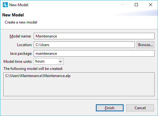
- Specify the location where you want to store your model files. Browse for the existing folder using the Browse button, or type the name of the folder you want to create in the Location edit box.
- Select the Model time units: hours.
- Click Finish to complete the process.
New model is created. It already has one agent type called
![]() Main and experiment called
Main and experiment called
 Simulation experiment.
In the center of the workspace you will see the graphical editor. It shows the diagram of the
![]() Main agent type. The blue frame on the diagram is the model frame that defines the size of the model window and the part of the graphical diagram that is shown in the window at the model runtime.
Main agent type. The blue frame on the diagram is the model frame that defines the size of the model window and the part of the graphical diagram that is shown in the window at the model runtime.
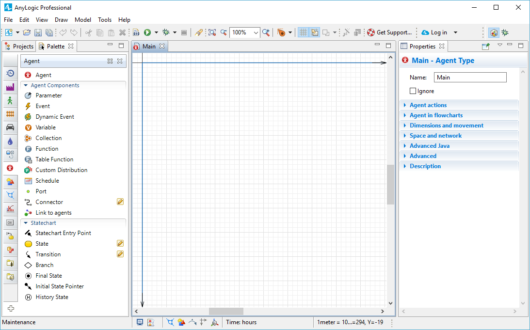
To the left of the graphical editor you can see the
 Projects view and the
 Palette view sharing the same area. The
Projects view provides access to AnyLogic models currently opened in the workspace. The workspace tree provides easy navigation throughout the models. The
Palette view contains all graphical elements you can add onto the graphical editor of your agent just by dragging and dropping. Model elements are grouped by categories in a number of stencils (palettes).
Palette view sharing the same area. The
Projects view provides access to AnyLogic models currently opened in the workspace. The workspace tree provides easy navigation throughout the models. The
Palette view contains all graphical elements you can add onto the graphical editor of your agent just by dragging and dropping. Model elements are grouped by categories in a number of stencils (palettes).
On the right side of the workspace you can see the
 Properties view. The
Properties view is used to view and modify the properties of a currently selected model element(s). When you select something — e.g., in the
Projects view or in the graphical editor — the
Properties view displays the properties of the selection.
Properties view. The
Properties view is used to view and modify the properties of a currently selected model element(s). When you select something — e.g., in the
Projects view or in the graphical editor — the
Properties view displays the properties of the selection.
Now we can continue developing our model created by AnyLogic model creation wizard.
First we need to create a single agent — the maintenance center, then an empty population for maintenance transport, three populations for the wind turbines, trucks, and helicopters, and an agent type to represent service requests. Then we will be able to define the processes inside the types of agents — on their diagrams.
Add a maintenance center
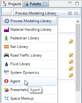
- In the
Palette view, hover your mouse over the vertical navigation bar on the left side of the view and select Agent there to open the
 Agent palette.
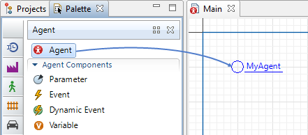
- Drag the
 Agent element from the
Agent palette into
Main diagram. The New agent wizard will pop up automatically.
Agent element from the
Agent palette into
Main diagram. The New agent wizard will pop up automatically.
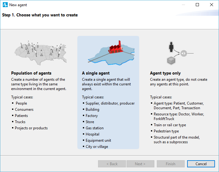
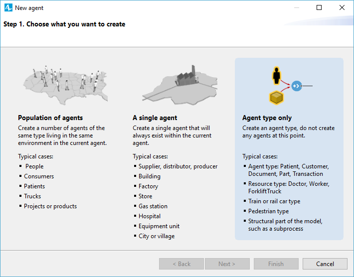
- Select A single agent option on Step 1. We need only one maintenance center that will send transport to turbines for scheduled maintenance and any failures/repairs.
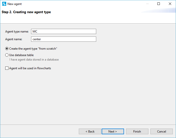
- We are creating a new type of agent and do not need to use any templates. Specify the Agent type name: MC and the Agent name: center. Click Next to proceed.
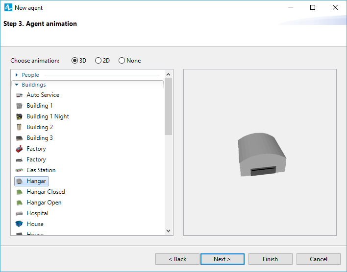
- Choose the 3D animation figure Hangar from the Buildings section and click Finish.
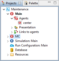
Now you can find the new agent type
![]() MC in the model tree on the same level as
MC in the model tree on the same level as
![]() Main and the agent
Main and the agent
![]() center itself under
center itself under
![]() Main >
Main >  Agents.
The agent animation is shown on the agent type diagram as well as on
![]() Main.
Main.
We want our agents to live in a continuous space, 1000x600 pixels, with a random layout. The agent populations that we will add on
![]() Main later will also live in the same space.
Main later will also live in the same space.
- Click
Main in the model tree.
- Expand the Space and network section of the Main agent type's properties.
- Set the space's Width to 1000, Height to 600. Then change the Layout type to Random.
Now we need to change the scale of the model and of this agent’s animation.
- Double-click
Main in the model tree and pan the agent’s diagram down.
- Above the X axis, you will find the Scale element. Open its
Properties view.
- Set the Scale is property to be Specified explicitly. Then specify the Scale: 5 pixels per kilometer.
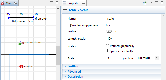
As you can see in the image above, if we will keep the animations of our agents resized corresponding to the model scale, these agents (such as maintenance center here) will become invisible in our model’s animation scene. So we will use greater scales for the agents to make them visible during the animation.
- Double-click
MC in the model tree.
- In the graphical editor, select the maintenance center animation shape, and in its properties, clear the Resize automatically to match agent scale option.
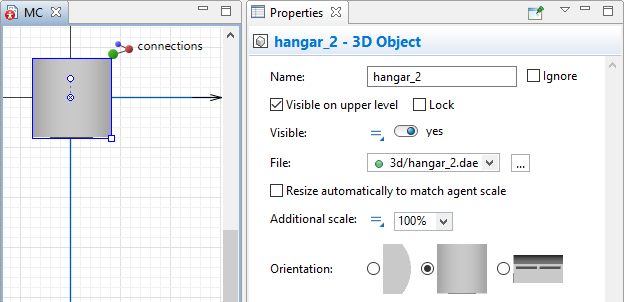
- Pan the agent’s diagram down and for the agent’s scale set the option Scale is: Specified explicitly. Then specify the Scale: 10 pixels per kilometer.
- Set the 3D object’s Additional scale to 75%.
Add the wind turbines
- Drag the
Agent element from the
Agent palette onto
Main diagram.
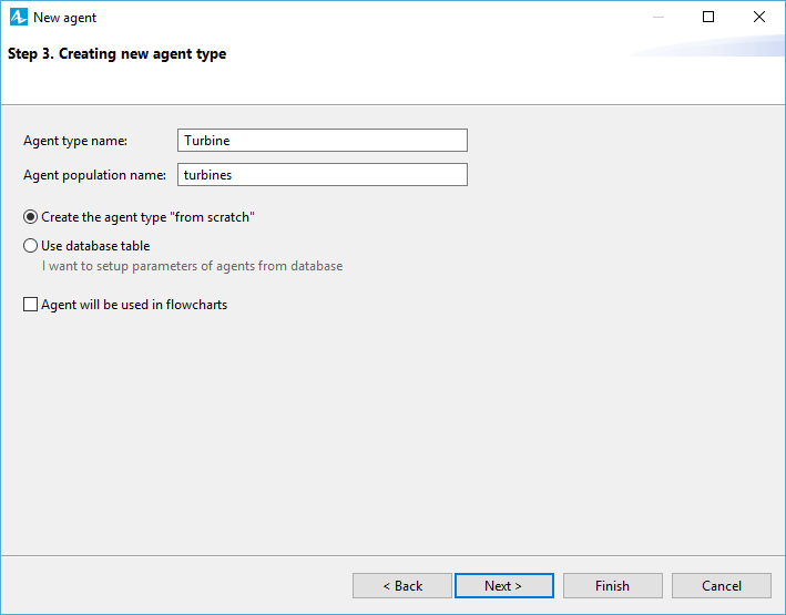
- This time, select Population of agents. Click Next on Step 2 (the default setting I want to create a new agent type). On the next wizard page type the name of the new type: Turbine and agent population name will auto-fill as turbines. Click Next.
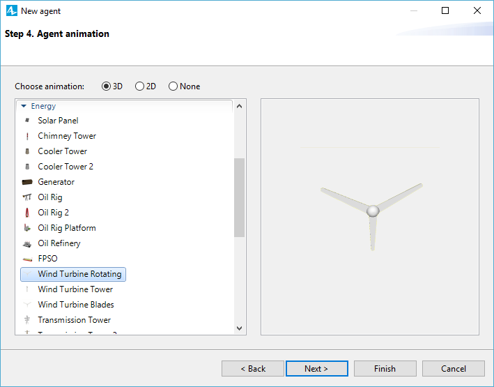
- Choose 3D animation figure Wind Turbine Rotating from the Energy section of the list.
- We do not need to add any parameters here, so skip Step 5.
- On Step 6, set up to create 25 agents in this population.
- Click Finish.
- Open the
Turbine agent diagram and set the agent’s Scale to 10 pixels per kilometer the same way we did for the
MC agent.
- We don’t want the animation of the turbine to resize automatically according to the change of the agent’s scale. This option is only applicable to individual 3D objects, but the Wind Turbine Rotating animation figure is a group comprised of several such objects, therefore we have to disable the Resize automatically to match agent scale option for each object individually.
Go to the Projects view and expand the Turbine > Presentation > level section to access the wind_turbine group. In the properties of wind_turbine_tower and wind_turbine_blades 3D objects disable the Resize automatically to match agent scale option. - For both these objects specify the Additional scale: 50%.
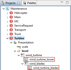
- Since we disabled the automatic resize option and changed the scale, we have to manually configure the alignment of elements that comprise the wind_blades group. In its properties change the code in Z property field to the following: 22.25 * Scale.DEFAULT_SCALE.pixelsPerUnit(METER).
Add the transport
- Drag the
Agent element from the
Agent palette onto
Main diagram.
- One more time select Population of agents. Click Next on Step 2 (I want to create a new agent type). On the next wizard page (step 3) define the Agent type name: Transport and the Agent population name: transport. Click Next.
- This is an empty population that does not need animation. We will use this agent type to define the logic of our model. Select None for animation type, skip the parameters step, select the Create initially empty population, I will add agents at model runtime option and click Finish.
Add trucks and helicopters to the model
- Drag the
Agent element from the
Agent palette onto
Main diagram.
- Again, select Population of agents. Click Next on Step 2 (I want to create a new agent type). On the next wizard page (step 3) define the Agent type name: Truck, and the agent population name will auto-fill as trucks. Click Next.
- Select the Lorry 3D animation figure from the section Road transport on the next step. We do not need to add any parameters here in the wizard. Set up the population to have 5 trucks.
- After you create the
Truck agent type, select it the model tree and go to its Properties view. First expand the Dimensions and movement section. We suppose that the average truck’s speed equals 70 kilometers per hour.
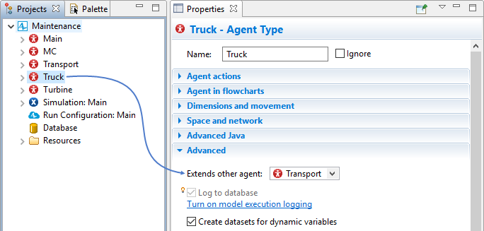
- Expand the Advanced section and make
Truck inherit
Transport configuration by setting up the parameter Extends other agent:
Transport.
- Select the truck animation shape, and in its properties, clear the Resize automatically to match agent scale option.
- Modify the
Truck scale. In the scale element properties, clear the Inherited from parent option and set the scale to 10 pixels per kilometer.
- Now
Truck agent is fully set up. We need to add one more population for helicopters. Go back to
Main and drag the
Agent element from the
Agent palette again and select Population on the first step.
- Type the new agent type name Helicopter and the population name helicopters will auto-fill. You can find the Helicopter 3D animation figure in the section Military. We want to use 2 helicopters for the turbine maintenance. This population lives in the same space.
-
Helicopter also Extends other agent:
Transport. We suppose that helicopters move with the speed 200 kilometers per hour.
- Select the helicopter animation shape, and in its properties, clear the Resize automatically to match agent scale option.
- Next, specify the Additional scale: 50%.
- Modify the Helicopter scale. In the scale element properties, clear the Inherited from parent option and set the scale to 5 pixels per kilometer.
Define service request pattern
- Drag the
Agent element from the
Agent palette into
Main diagram.
- Select Agent type only. We need to add an agent type to define logic of the model with the parameters we will set up on its diagram.
- Type its name ServiceRequest in the corresponding field and click Next. Select None for the animation type and proceed to the next step.
- On step 4 we will create a parameter and an option list.
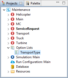
Option List is the element for defining agent attributes that have limited choice of alternative options. In our case, we need to differentiate between trucks and helicopters which are both used by the maintenance center and respond to the service requests. The parameter is called type and its type is the Option List. Since there are no option lists in the model yet, the wizard suggests that you create a new option list: TransportType. Type the options in the table, one per line: AUTO, AVIA.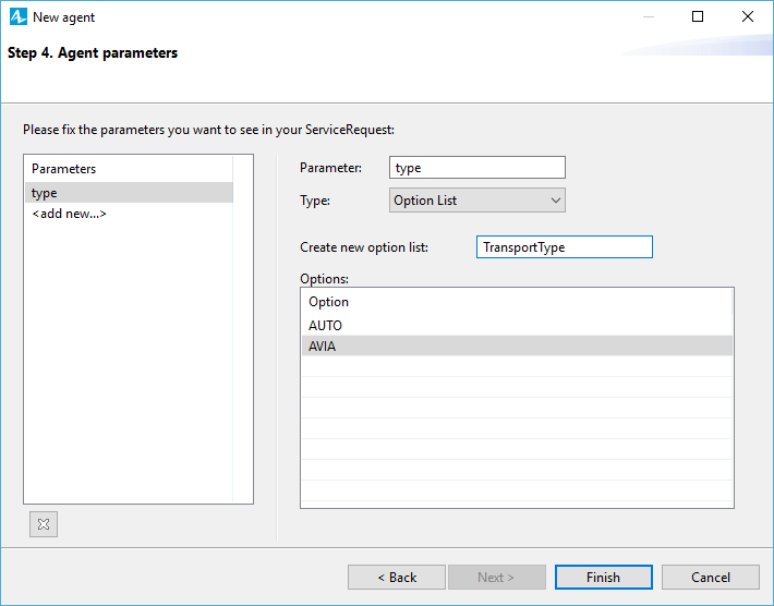
- Click Finish. The option lists do not have any graphical icons that you can click to select them in the graphical editor. You can find Option Lists in the model elements tree:
- After you click Finish, AnyLogic will open the
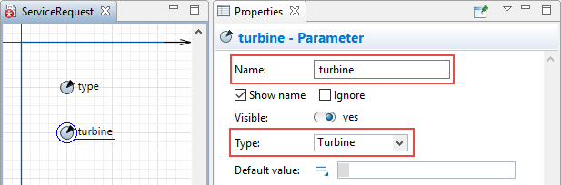
ServiceRequest agent type diagram. There you can find the parameter type that we have created. Add one more
 Parameter from the
Agent palette. Call it turbine and select its Type from the drop-down list: Turbine. Now
ServiceRequest is fully set up.
Parameter from the
Agent palette. Call it turbine and select its Type from the drop-down list: Turbine. Now
ServiceRequest is fully set up.
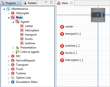
The agent elements will appear on
![]() Main. You can notice that the populations are marked with the [..]. Move the agents beyond the model window and place the center of each animation figure in the axis origin.
Main. You can notice that the populations are marked with the [..]. Move the agents beyond the model window and place the center of each animation figure in the axis origin.
You can find the space settings in the properties of
![]() Main, section Space and network.
Main, section Space and network.
Run the model
- Build your project by clicking the
 Build model toolbar button. If there are some errors in your model, the building fails and the Problems view appears listing all the errors found in your model. Double-click an error in the list to open the location of the error and fix it. After the model is successfully built, you can start it. Running the simulation, you automatically bring the current model up to date.
 - Choose the experiment you want to run from the drop-down list of the
 Run toolbar button. Your simulation experiment is called
  Maintenance/Simulation. Later on you can use the
Run toolbar button to start the previously run experiment.
Maintenance/Simulation. Later on you can use the
Run toolbar button to start the previously run experiment. - Having started the model, you will see the presentation of your top-level agent type
Main. Since we have only started developing the model, at this moment we can see the maintenance center, turbines, and our transport distributed randomly in the continuous space.
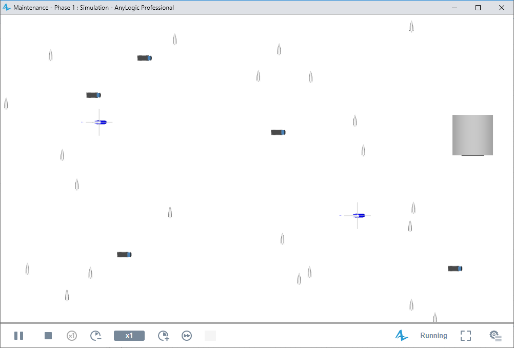
Next, we will place the transport — trucks and helicopters — in the maintenance center.
-
How can we improve this article?
-