

Now we want to create 3D animation for our model.
First of all you should add 3D window to your
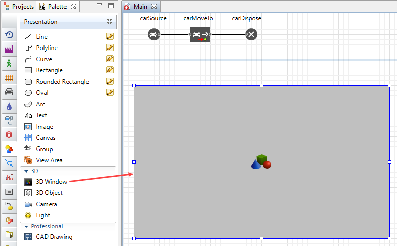
![]() Main diagram. 3D window plays the role of a placeholder for 3D animation. It defines the area on the presentation diagram where 3D animation will be shown at runtime.
Main diagram. 3D window plays the role of a placeholder for 3D animation. It defines the area on the presentation diagram where 3D animation will be shown at runtime.
Add 3D window
- Drag the
 3D Window element from the 3D section of the
 Presentation palette to the graphical editor.
 - The grey area will appear on the screen. Locate it where you want your 3D presentation to be shown at the model runtime. In our model the layout takes most of the place inside the model window (the blue rectangular frame you see in the graphical editor denotes the border of the model window). Let’s place the 3D window below the layout. At the model runtime we will navigate to 3D animation using AnyLogic built-in navigation tool.
Now you can run your model and observe simple 3D animation.
Navigating through 3D animation
- Run the model.
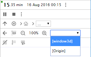
When you create a 3D window, AnyLogic adds a view area that allows you to easily navigate to the 3D view at runtime. To switch to this 3D view while the model is running, open the developer panel by clicking the Developer panel control in the right corner of the control panel. In the developer panel, expand the
  select view area to navigate list and select [window3d] from the list.
- You will see 3D animation. By default cars are shown in 3D animation as colored parallelepipeds.
- Navigate through the 3D scene using the commands described below.
| In order to | Use the mouse as described here |
|---|---|
| Move the scene | 1. Press the left mouse button in the 3D view and hold the mouse button pressed. 2. Move the mouse in the required direction. |
| Rotate the scene | 1. Press Alt key (macOS: Option key) and hold it pressed. 2. Click in the 3D scene window and, while holding Alt and the left mouse button down. 3. Move the mouse in the required rotation direction. |
| Zoom in/out the scene | 1. Scroll the mouse wheel in the 3D window away from / towards you. |
Now we want to set a specific 3D animation shape for cars instead of the default one that is currently being used. This requires us creating a custom car type.
Create a new car type
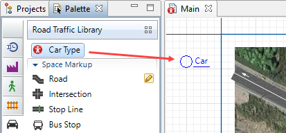
- Open the
 Road Traffic Library palette.
 - Drag the
 Car type element into the graphical editor.
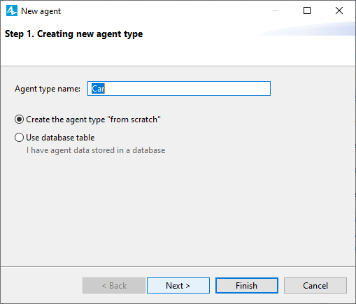
- The New agent wizard will open on the Creating new agent type step. Leave Car as the Agent type name, and click Next.
- On the next page of the wizard you will be prompted to choose animation figure for this agent. Since we want to choose a 3D figure, leave the 3D option selected. Select Car from the list of 3D figures below.
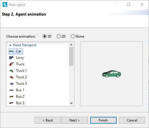
- Click Finish. The new
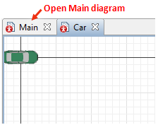
Car diagram will open. You can find the car figure in the axis origin. Switch back to the
Main diagram.
Configure the flowchart to use the new car type
- On the
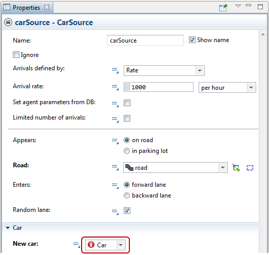
Main diagram, select the carSource block in the graphical editor.
- In the Properties view expand Car section and choose
Car in the New car drop-down list.
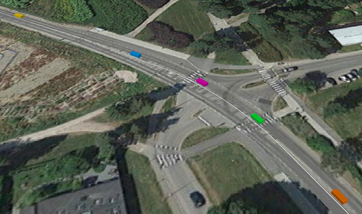
- Run the model and switch to 3D view to see our cars moving along the road in 3D animation.
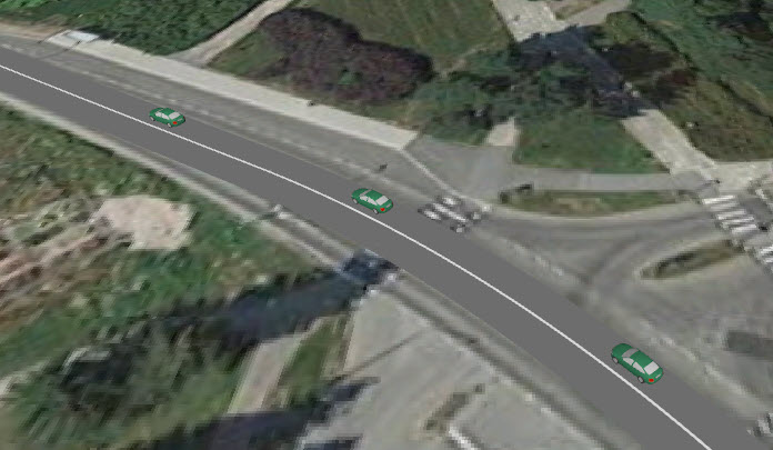
You can see that the layout and the road are drawn interlaced sometimes. Apart from that, the color of our road is similar to the color of the road on the layout which makes them merge.
We will make a few adjustments in our model to avoid interlacing and make animation look more attractive.
Change the background color of the drawn road network
- Select the road network with two consecutive clicks on the road (the first click will select the road itself, while the second click will select the road network).
- Open the Appearance section in the road network’s Properties. Click on the Road color control element and choose Textures... from the drop-down menu.
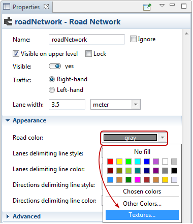
- Choose tarmac texture in the Textures dialog box.
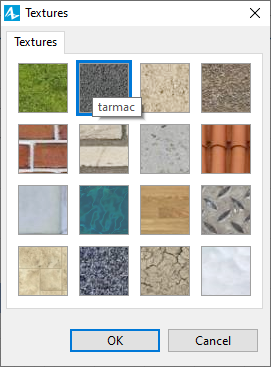
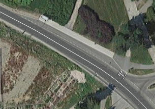
The drawn road will now differ in color from the road on the layout.
Now we need to fix the interlacing issue that can be observed in 3D mode. The source of the problem is in the same Z-level of the road network and the layout image (0). This is why they overlay each other in turns.
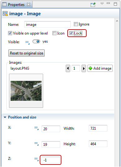
Adjust Z-level of the image
- Click on the layout in the graphical editor.
- Open the Position and size section of the layout’s properties and type -1 in the Z parameter.
- Select the Lock check box in the Properties view to lock the image. Locked shapes do not react to mouse clicks — it is impossible to select them in the graphical editor until you unlock them. Locking the image helps us prevent accidental image editing while drawing shapes over it.
Congratulations on completing the second phase. In the next phase we will draw one more road and model car movement on the automatically created intersection.
Demo model: Road Traffic Tutorial — Phase 2 Open the model page in AnyLogic Cloud. There you can run the model or download it (by clicking Model source files). Demo model: Road Traffic Tutorial — Phase 2Open the model in your AnyLogic desktop installation.-
How can we improve this article?
-