

Pipe is the space markup element used to graphically draw pipes in fluid simulation models.
It is the animation shape for a pipe defined logically with Fluid Library block Pipeline. You draw the Pipe according to the pipe topology, and customize its appearance via the pipe’s properties (namely, set its color, diameter, and optionally alter Z-coordinates). Pipeline block defines all the logic for the pipe (its capacity, rate, initial amount of liquid inside the pipe, color of batches flowing through the pipe, etc.).
Pipe is displayed both in 2D and 3D animation (to see the pipe in 3D, add 3D window in your model). Pipe may have turning points and contain several segments, see the figure below.
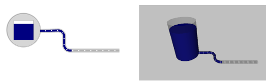 Pipe leading from a storage tank, in 2D and 3D animation
At model runtime batches flowing through the pipe will be animated as cylinders moving inside the pipe cylinder. The color of liquid cylinders is not defined in the pipe shape, but it is defined in the Fluid Library flowchart.
The pipe has start point and end point. The liquid will always flow from the pipe’s start point to its end point, so the pipe direction is very important. Pipe end points can be put at storage tanks, or left just “hanging”.
Demo model: Pipeline Open the model page in AnyLogic Cloud. There you can run the model or download it (by clicking Model source files). Demo model: PipelineOpen the model in your AnyLogic desktop installation.To draw a pipe
-
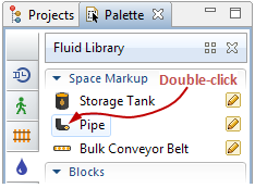
Double-click the Pipe
 element in the Space Markup section of the
  Fluid Library palette. The icon of the element should turn into
  . It means that the drawing mode is activated and now you can draw a pipe in the graphical editor point by point.
-
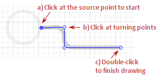
Draw the pipe in the graphical editor:
- Click in the graphical editor to draw the first point of the pipe. Please mind that the liquid will always flow from the pipe’s start point to its end point, so put the first point at the liquid source location.
- If the pipe is not straight, but has turning point(s), add these points by making more mouse clicks in the turning points. Each click adds one more pipe segment.
- Finally put the final point of the pipe with the double-click at the liquid receiver point.
-
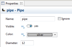
Having finished drawing the pipe, customize its appearance. In the Properties view, set the pipe’s Color and Diameter (in pixels).
- If your model has 3D animation, and this pipe leads in/out of some storage tank, you may need to finely adjust the Z-coordinates of pipe and tank. For instance, if the storage tank’s Z-coordinate is 0, and you want the pipe to go out of its bottom, open the pipe’s Position and size properties, and specify the pipe’s radius value as the pipe’s Z-coordinate (e.g. if the pipe’s Diameter is 8, specify 4 in the Z field.)
- If the pipe is not lying on one height, you can modify the Z-coordinates of the pipe points in the Points section of pipe’s properties.
- Set this pipe as the animation shape for the Pipeline flowchart block. Open the Animation section of the Pipeline properties, and select the name of this pipe in the Pipe control.
- General
-
Name — The name of the pipe. The name is used to refer to the pipe from the Pipeline block properties.
Ignore — If selected, the pipe is excluded from the model.
Visible on upper agent — If selected, the pipe is also visible on the upper agent where this agent lives.
Lock — If selected, the pipe is locked. Locked shapes do not react to mouse clicks — it is impossible to select them in the graphical editor until you unlock them.
Visible — Here you specify whether the shape is visible on animation at model runtime, or not. Using the control, choose yes or no.
Color — Here you can set the pipe color.
Diameter — Here you can set the pipe diameter, in pixels.
- Position and size
-
Level — Level to which this element belongs.
X — X-coordinate of the pipe’s start point.
Y — Y-coordinate of the pipe’s start point.
Z — [Enabled if the shape is visible in 3D (advanced property Show in is set to 2D and 3D or 3D only)] Z-coordinate of the pipe’s start point.
- Points
-
The table located in the Points properties section enables users to view and adjust coordinates of the pipe turning points. It is the place where you can adjust the Z coordinates for some pipe points.
Here you define relative coordinates, not the absolute ones. The first point always has coordinates (0, 0, 0) that cannot be changed.
Other rows of the table define relative coordinates of the successive points. Coordinates of each point are actually offsets of the corresponding point from the start point along X, Y (and optionally Z) axes correspondingly.
- Advanced
-
Show in — Here you can choose whether you want the pipe to be shown both in 2D and 3D animation, or in 2D only, or in 3D only.
Show name — If selected, the pipe’s name is displayed on the graphical diagram.
You can modify the drawn pipe: change the pipe direction, add new turning points and remove the existing points, split the pipe into two separate pipes, or continue drawing the pipe by adding more segments to one of its end points.
The pipe has direction. The liquid will always flow from the pipe’s start point to its end point. So it is important when you draw your pipe, where you put the pipe’s start point. However, you can always change the pipe direction (see below).
To find out the direction of the pipe
- Select the pipe in the graphical editor with a mouse click.
- The start point will be highlighted with blue, and the pipe’s direction will be indicated with arrows.
To change the direction of the pipe
- Right-click the pipe in the graphical editor and choose Change Direction from the context menu. You will see that the arrows changed their directions.
To continue drawing an existing pipe by adding more segments
- Right-click the pipe in the graphical editor and select Append Line from the context menu.
- You can append a line to any end point of the pipe. Click one of two pipe’s end points where you want to append more pipe segments.
- Now you can continue drawing the pipe: add new segments by clicking in the graphical editor, and finish drawing by putting the end point with the double-click.
To add a new salient point
- Double-click the pipe’s segment where you want to add a new turning point.
- You will see the new point created. Now you can move the point by dragging and finally create the pipe of the required form.
To remove a salient point
- Double-click the pipe’s salient point. The point will disappear. If you double-click the end point of the pipe, the last segment on this edge will be deleted.
You may want to split a pipe into several pipes (for example, to put a valve inside).
To split one pipe into two pipes
- Right-click the pipe in the graphical editor and select the option Split into Two Shapes from the context menu.
- You will see that the pipe’s salient points are highlighted. Click the point where you want to split the pipe. The pipe will be split into two separate pipes.
You can dynamically modify shape properties at model runtime using the following API.
- Dimensions
-
Function Description double getDiameter() Returns the diameter of the pipe (in pixels). double length() Returns the length of the pipe (in pixels). double length(LengthUnits units) Returns the length of the pipe in the specified length measurement units.
units — a constant defining the length units.void setDiameter(double diameter) Sets the diameter of the pipe.
diameter — the new diameter of the pipe (in pixels). - Points
-
Function Description Point getStartPoint() Returns the Point object with coordinates of the pipe’s starting point. Point getStartPoint(Point out) Returns the Point object with coordinates of the pipe’s starting point.
out — output object to write to, may be null.Point getEndPoint() Returns the Point object with coordinates of the pipe’s ending point. Point getEndPoint(Point out) Returns the Point object with coordinates of the pipe’s ending point.
out — output object to write to, may be null.Position getStartPosition() Returns the Position object with coordinates and orientation of the pipe’s starting point. Position getStartPosition(Position out) Returns the Position object with coordinates and orientation of the pipe’s starting point.
out — null.Position getEndPosition() Returns the Position object with coordinates and orientation of the pipe’s ending point. Position getEndPosition(Position out) Returns the Position object with coordinates and orientation of the pipe’s ending point.
out — output object to write to, may be null.Point getPointAtOffset(double offset, Point out) Returns the Point object with coordinates and orientation of the point that is located at the given offset distance (in pixels) from the pipe’s starting point.
offset — offset, non-negative value, should be less or equal to the full length.
out — output object to write to, may be null.Point getPointAtOffset(double offset, LengthUnits units, Point out) Returns the Point object with coordinates and orientation of the point that is located at the given offset distance from the pipe’s starting point.
offset — offset, non-negative value, should be less or equal to the full length.
units — one of the chosen length units.
out — output object to write to, may be null.Position getPositionAtOffset(double offset, Position out) Returns the Position object with coordinates and orientation of the point that is located at the given offset distance (in pixels) from the pipe’s starting point.
offset — offset, non-negative value, should be less or equal to the full length.
out — output object to write to, may be null.Position getPositionAtOffset(double offset, LengthUnits units, Position out) Returns the Position object with coordinates and orientation of the point that is located at the given offset distance from the pipe’s starting point.
offset — offset, non-negative value, should be less or equal to the full length.
units — one of the chosen length units.
out — output object to write to, may be null.boolean contains(double px, double py) Returns true if the pipe contains the point with the given coordinates.
px — the X-coordinate of the point.
py — the Y-coordinate of the point.boolean contains(double px, double py, double distance) Returns true if the pipe contains the point with the given coordinates using the given distance tolerance; returns false otherwise.
px — the X-coordinate of the point.
py — the Y-coordinate of the point.
distance — distance tolerance to determine whether the given point lies within the markup element line proximity.boolean containsSq(double px, double py, double squareDistance) Returns true if the pipe contains the point with the given coordinates using the given square distance tolerance; returns false otherwise.
px — the X-coordinate of the point.
py — the Y-coordinate of the point.
squareDistance — the square of distance tolerance to determine whether the given point lies within the markup element line proximity. - Segments
-
Function Description int getSegmentCount() Returns the number of the pipe’s segments. MarkupSegment getSegment(int index) Returns the segment by the provided index.
index — the segment index, starting from zero up until the number of segments - 1. - Level
-
Function Description Level getLevel() Returns the level on which this pipe is located. - Appearance
-
Function Description Color getColor() Returns the color of the markup element, or null if markup element has no color or has textured (in this case use getTexture() to get the shape’s texture). void setColor(Color color) Sets the color of the pipe shape.
color — the new color. If null is passed, the pipe shape is not drawn.void setColor(Paint color) Sets the color of the pipe shape.
color —the new color. If null is passed, the pipe shape is not drawn.Texture getTexture() Returns the texture of the pipe element if it has texture. - Visibility
-
Function Description boolean isVisible() Returns true is the pipe shape is visible; returns false otherwise. void setVisible(boolean v) Sets the visibility of the pipe shape.
v — visibility. If v is true, the shape is set to be visible; if v is false, the shape is set to be invisible. - Removal
-
Function Description void remove() Removes the pipe from the presentation. If the pipe is not a part of presentation, the function does nothing.
Removal from the presentation does not necessarily mean removing from the model logic, since logical networks and routes may have been created before the removal and survive it.
-
How can we improve this article?
-