

Pathway is used to restrain pedestrian movement with a walking corridor. When moving along the pathway, pedestrians try to keep within the pathway bounds. However, if the pathway is overcrowded, pedestrians may easily cross its borders and walk nearby. Pathway borders do not act as walls. Pathway just defines the movement guideline.
One of the most frequent use cases of the pathway is separating opposite pedestrian flows, e.g. in underground passage. Assume we have the following passage with two pedestrian flows moving in opposite directions. To avoid flows intersection, passengers try to keep specific sides while moving (e.g. they keep the left side). We can simulate this by drawing two pathways, one for each pedestrian flow. Draw the pathways inside the passage, along the opposite walls.
To make pedestrians move within the bounds of these pathways, configure PedGoTo blocks in your flowchart (PedGoTo block simulates the pedestrian movement). Choose the Follow route as the block’s Mode and specify the pathway name in its Route property.
Demo model: PedGoTo Open the model page in AnyLogic Cloud. There you can run the model or download it (by clicking Model source files). Demo model: PedGoToOpen the model in your AnyLogic desktop installation.To draw a pedestrian pathway
- Double-click the
 Pathway element in the Space Markup section of the
  Pedestrian Library palette.
 - The icon of the element should turn into
 . It means that the drawing mode is activated and now you can draw pathway in the graphical editor point by point.
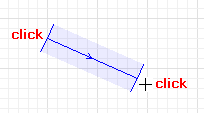
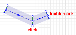
 - Click in the graphical editor to put the first point of the pathway. Do more clicks where you want to pathway’s turn point.
- Add the last point with double-clicking.
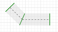
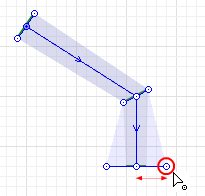
- You can change the shape of the pathway anytime. Left-click a middle point, hold the mouse button and drag a part of the pathway there where you need it, making it longer or shorter.
- You can adjust the width by dragging the side points.
- General
-
Name — The name of the pathway. The name is used to identify and access the pathway from code and flowchart blocks properties.
Ignore — If selected, the pathway is excluded from the model.
Visible on upper agent — If selected, the pathway is also visible on the upper agent where this agent lives.
Lock — If selected, the pathway is locked. Locked shapes do not react to mouse clicks — it is impossible to select them in the graphical editor until you unlock them.
Visible — Here you specify whether the shape is visible on the animation at the model runtime, or not. Using the control, choose yes or no.
Line color — The pathway color.
Level — The level this pathway belongs to.
- Advanced
-
Show in — Here you can choose whether you want the shape to be shown both In 2D and 3D animation, or in 2D only, or in 3D only.
Show name — If selected, the pathway’s name is displayed on the graphical diagram.
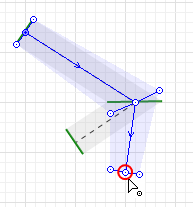
Each pathway has direction. To know the direction of the pathway, select it in the graphical diagram with a mouse click.
You can change the direction anytime in one click. Just one case when you may need this. You have drawn a pathway passing through a passage of a complex form.
To change the direction of the pathway
- Right-click the pathway in the graphical diagram and choose Change direction from the context menu. You will see that the arrows will change their directions.
- Color
-
Function Description Color getLineColor() Returns the color of the shape. void setLineColor(Color color) Sets the color of the shape.
color — the new color - Visibility
-
Function Description boolean isVisible() Returns true if the shape is visible; returns false otherwise. void setVisible(boolean v) Sets the visibility of the shape.
v — visibility. If v is true — the shape is set to be visible, if it is false — not visible. - Level
-
Function Description Level getLevel() Returns the level this space markup shape belongs to. - Removal
-
Function Description void remove() Removes the pathway from the presentation. If the pathway is not a part of presentation, the function does nothing. Note, that removal from the presentation does not necessarily mean removing from the model logic, since logical networks and routes may have been created before the removal and survive it.
-
How can we improve this article?
-