

AnyLogic not only supports laying out complex SD models using sectors, but also naturally offers all benefits of object-oriented approach to system dynamics modelers. You can define complex models in hierarchical manner where logically separate parts of the stock and flow diagram are encapsulated into different agent types and expose only their interface variables (as inputs or outputs).
System dynamics components can be packaged into AnyLogic agent types, parameterized, organized in various structures, and reused.
Demo model: Population Open the model page in AnyLogic Cloud. There you can run the model or download it (by clicking Model source files). Demo model: PopulationOpen the model in your AnyLogic desktop installation.Take a look into the given sample model to understand how you can lay out your SD model in an hierarchical way.
This model has two logical parts, each focusing on a particular aspect, housing sector and population sector. The stock-and-flow diagram for each part is drawn apart from others, in the separate agent type: HousingSector and PopulationSector.
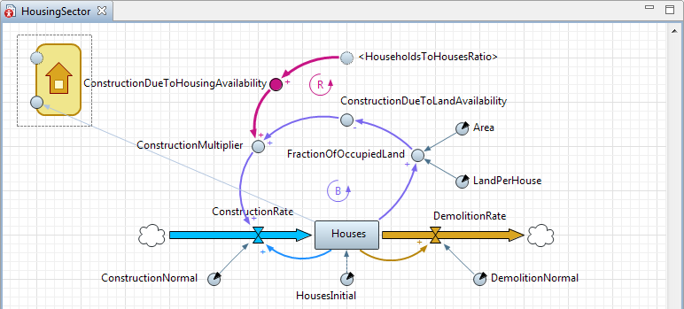 HousingSector diagram
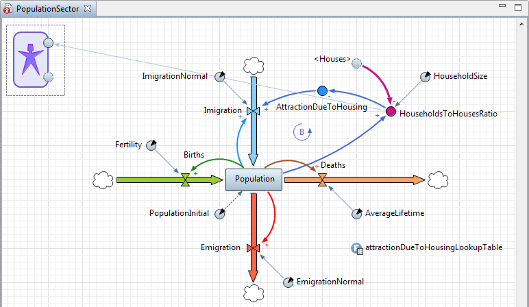 PopulationSector diagram
In AnyLogic you can partition the model into components in object-oriented way by using agents exposing the “input” and “output” dynamic variables as a part of their interface.
The “interface” between the sectors includes two variables:
- The Houses stock from the Housing sector is used in the Population sector.
- The HouseholdsToHousesRatio variable from the Population sector is used in the Housing sector.
Each variable may have one “original” instance and multiple “shadow” copies in the other sectors.
Let us explain how the interface variables were created.
Creation of the “output” interface variable for Houses
- Drag the
 Dynamic Variable element from the
  System Dynamics palette onto the HousingSector diagram.
 - Name this variable HousesOut.
- For this variable, select the Visible on upper agent check box. This way we declare this variable as an interface variable that will be visible in the agent that will link two parts together (in Main).
- In the HousesOut= field, set the variable’s value to Houses. This is how we tell the variable to take the value of the Houses stock (and expose it to the agent’s interface).
Creation of the shadow variable for another interface variable, HouseholdsToHousesRatio
- Drag the
 Shadow element from the System Dynamics palette onto the HousingSector canvas.
 - Select the "original" variable HouseholdsToHousesRatio from the list.
Create the housing sector’s interface
- Draw the icon for this agent type with presentation shapes.
- For all icon shapes, select the Icon check box in their properties.
- Place the HousesOut variable on the icon border.
- Draw the link going from Houses to HousesOut.
- Move the “original” variable HouseholdsToHousesRatio onto the icon border.
- In the properties of this variable, select the option Visible on upper agent to expose this variable on the agent’s interface.
- Select the Dependent check box. This way we tell this variable that it will get its value “from outside”, in our case — from the external interface variable of the population sector that will be connected to it on the Main diagram.
- Reconnect the link from this variable to its shadow, <HouseholdsToHousesRatio> to make the stock-and-flow diagram look neat.
Repeat these actions on the PopulationSector diagram. Then drag both HousingSector and PopulationSector agents from the Projects tree on the Main diagram and connect their interface variables together with connectors as shown below:
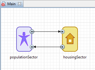
This image gives you the idea how values are passed from one sector to another via the interface variables we’ve created.
-
How can we improve this article?
-