

In the first phase we will create a new model and populate it with buildings that will be subject to bombing.
Create a new model
- Click the
 New toolbar button toolbar button. The New Model dialog box will be displayed.
 -
Define the parameters of the new model:
- Specify the name of the model in the Model name field. Type Air Defense System.
- Set the new model location if necessary by clicking the Browse button and selecting the required folder.
- Set Model time units to seconds.
- Click Finish to create a new model.
We’ll begin the design our model with creating a new population of agents that will represent 10 facilities.
Create a new population of agents
- Drag the
 Agent element from the
 Agent palette onto the
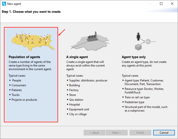
Main diagram. The New agent dialog box will open.
Agent palette onto the
Main diagram. The New agent dialog box will open. - Click Population of agents. You will be taken to the next step of the New agent wizard.
-
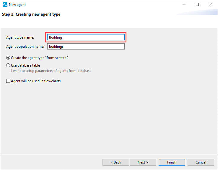
Type Building in the Agent type name field. The Agent population name will be automatically filled. Click Next to proceed to step 3.
-
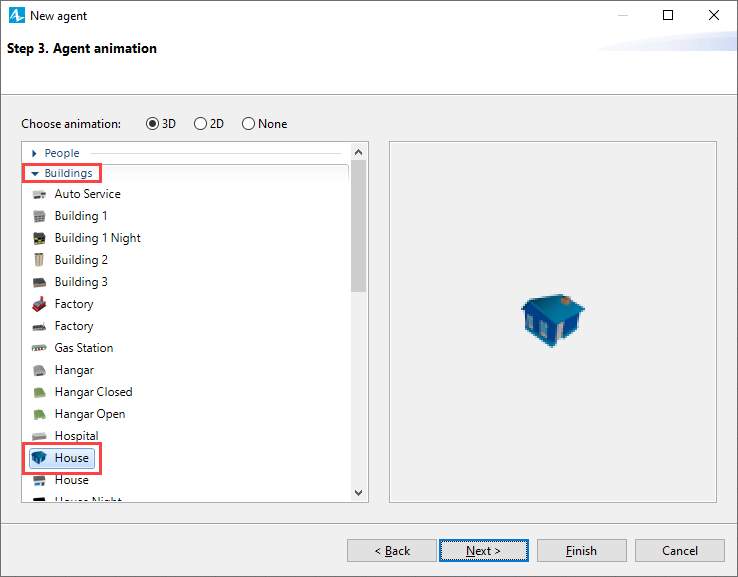
Leave the Choose animation parameter set to 3D mode and choose the House animation shape in the Buildings section. Click Next to proceed to step 4.
- We will not set any agent parameters, you may click Next to proceed to step 5.
-
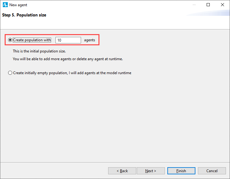
Set the Create population with parameter to 10. Click Next to proceed to step 6.
-
Leave the Space type parameter set to Continuous and select the Apply random layout option.
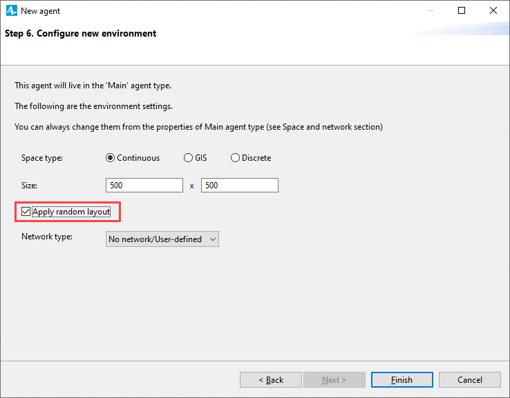
- Click Finish to save the changes and create the customized population.
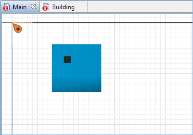
We have created a population of agents and defined animation shape for them.
Adjust the scale of the model
-
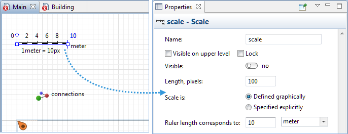
Click the Scale element on the
Main diagram to open its Properties.
-
Set the Ruler length corresponds to parameter to 100. The scale on the ruler will change.
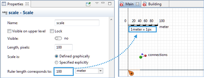
We modified the scale of the model, as a result the building shape changed its size. As you can see in the image above, if we will keep the animations of our agents resized corresponding to the model scale, these agents (such as building here) will become invisible in our model’s animation scene. So we will use greater scales for the agents to make them visible during the animation.
We have completed setting up the population of agents and may now run our model for the first time to observe the model behavior.
Run the model
-
Click the
 Run toolbar button.
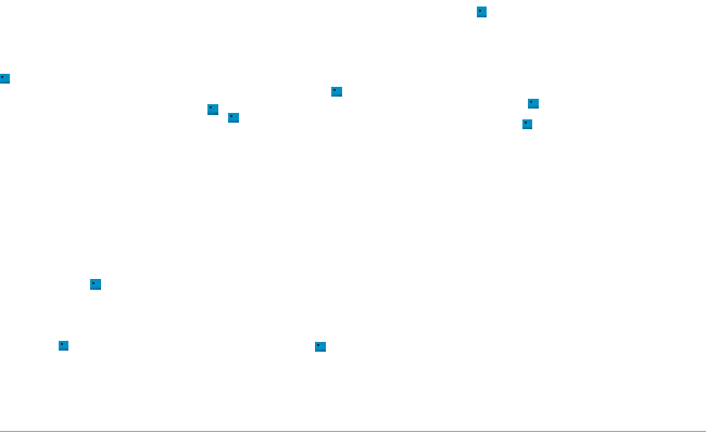
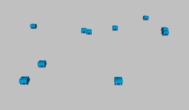
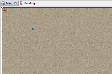
The model window will appear and the model will launch automatically. You will see the 10 building shapes randomly distributed in a 500 by 500 pixel space. This is the space size set by default. We do not need to change it as we will customize the location of the facilities.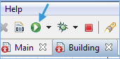
Now we will create 3D animation for our model. First of all we need to add 3D window to our
![]() Main diagram. The 3D window plays the role of a placeholder for 3D animation. It defines the area on the presentation diagram where 3D animation will be shown at runtime.
Main diagram. The 3D window plays the role of a placeholder for 3D animation. It defines the area on the presentation diagram where 3D animation will be shown at runtime.
Add 3D window
-
Drag the
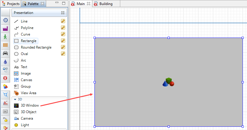
 3D Window element from the 3D section of the Presentation palette to the graphical editor. Place the window below the model window frame.
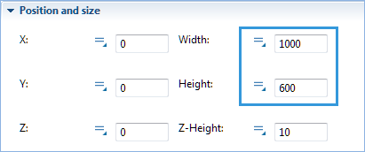
-
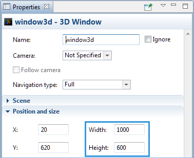
Navigate to the Properties view of the 3D window and set its Width and Height parameters to 1000 and 600 respectively.
Now we will run the model and switch between the 2D and 3D views in the model window.
Compare 2D and 3D views
- Click Run in the toolbar to run the model.
-
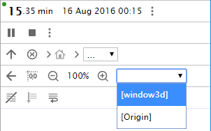
When you create a 3D window, AnyLogic adds a view area that allows you to easily navigate to the 3D view at runtime. To switch to this 3D view while the model is running, open the developer panel by clicking the Developer panel
 control in the right corner of the control panel. In the developer panel, expand the
  select view area to navigate list and select [window3d] from the list.
-
The view mode will change to 3D.
Draw the surface
-
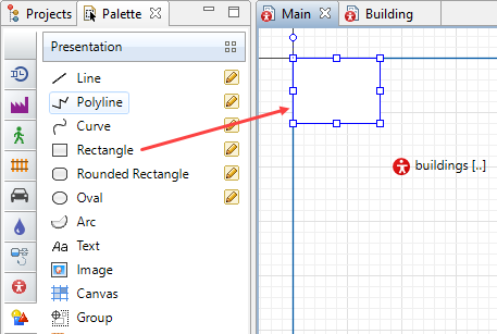
Drag a
 Rectangle shape from the Presentation palette onto the editor of
Main, place its top left corner at (0,0).
Rectangle shape from the Presentation palette onto the editor of
Main, place its top left corner at (0,0).
-
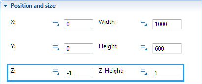
Navigate to the Position and size section of the rectangle’s Properties and set its Width and Height parameters to 1000 and 600 respectively, hence the area size is 1000*600 meters.
-
Now set the Z and Z-Height parameters to -1 and 1 respectively.
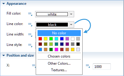
- In the Appearance section of the rectangle’s Properties set the Line color option to No color.
- Now we will define the texture of the rectangle area. Click the Fill color control and select Textures to open a dialog box with available textures.
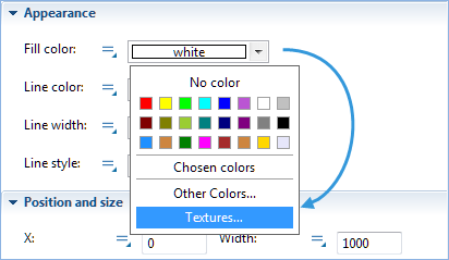
- Click Earth texture to set it as the fill color for the rectangle shape.
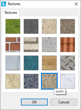
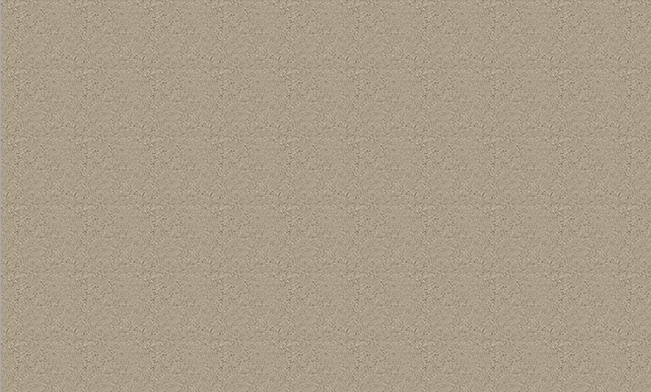
- Click OK to close the dialog box. The rectangle shape will change it appearance.
Now run the model and observe the new layout both in 2D and 3D modes.
Observe the new layout
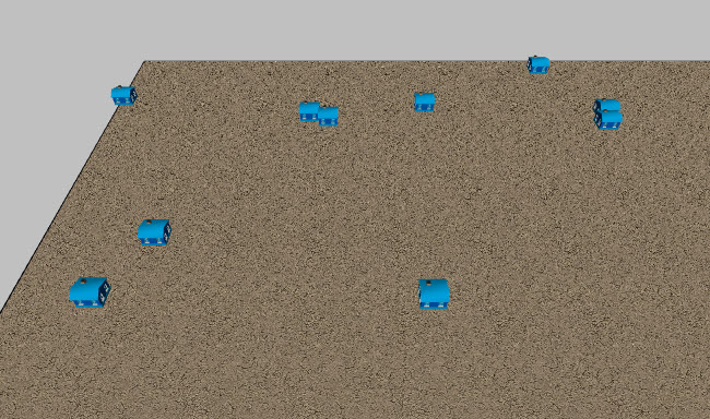
- Run the model. You will observe the model in the 2D view. As you can see, we have the new layout here but no buildings can be seen.
- Switch to 3D animation scene. You can observe buildings in 3D view.
In order to make buildings visible in the 2D view we must reorder the shapes in the design.
Reorder shapes
-
Right-click the rectangle shape to open its context menu. Then click the Order menu item and select the Sent to Back sub-item from the list of available orders.
The 2D building shape will now be visible.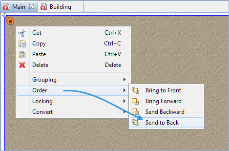
Now the model should have correct visualization in both 2D and 3D view. Prior to running the model to check if everything works like it should, we will lock the Rectangle shape and add camera.
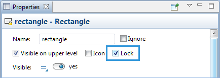
Lock the rectangle shape
-
In the Properties view select the Lock option to lock the shape. This will prevent occasional selection of the rectangle while working with other elements on the diagram.
Add a camera
- Drag the
 Camera element from the 3D section of the
 Presentation palette onto the graphical editor. You will see the camera icon in the graphical editor.
 - Direct the camera at the buildings presentation shapes (the positioning is described in details in the Camera article).
It is time to run the model and adjust the camera position to the desired one. We will save that position afterwards to have the camera always located at the set position.
Adjust the camera position
- Run the model and switch to 3D mode.
- Right-click the 3D model presentation to open a pop-up menu. Navigate to the Camera menu item and select camera sub-item. You will switch to the camera view.
- Position the camera to have the best possible picture while observing the model in the runtime (for more details on navigating the 3D scene, see Moving and rotating 3D scene at runtime).
- When done, right-click the 3D model presentation and click Copy camera’s location.
You may stop the simulation now. We have set up our camera and copied its position, now we need to apply the new camera position.
Apply new camera position
- Click the Camera element to open its Properties view.
- Click the Paste coordinates from clipboard button in the Properties view. The rotation parameters will change.
In the last step of this phase we will create a protected area, within which the buildings will be placed. The area will further be equipped with the air defense system, eliminating the air attacks on our facilities.
Define protected area
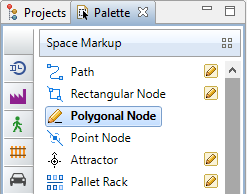
- Double-click the
 Polygonal Node element in the
 Process Modeling Library palette to activate drawing mode.
- Click on top of the rectangle to start drawing the protected area.
- Finish drawing with a double-click on the last node.
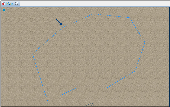
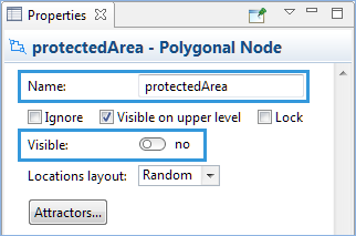
- Navigate to the element’s Properties, name it protectedArea and set its Visible parameter to no.
We have created a new area, now we need to locate our facilities within its boundaries.
Relocate the facilities
- Click the
buildings population on the
Main diagram to open the Properties view.
- Navigate to the Initial location section and set the Place agent(s) parameter to in the node. The Node parameter will appear below.
- Click the set by default None value for the Node parameter and select
 protectedArea from the drop-down list of available nodes.
 - Now open the properties of
Main and navigate to the Space and network section.
- Set the Layout type to User-defined.
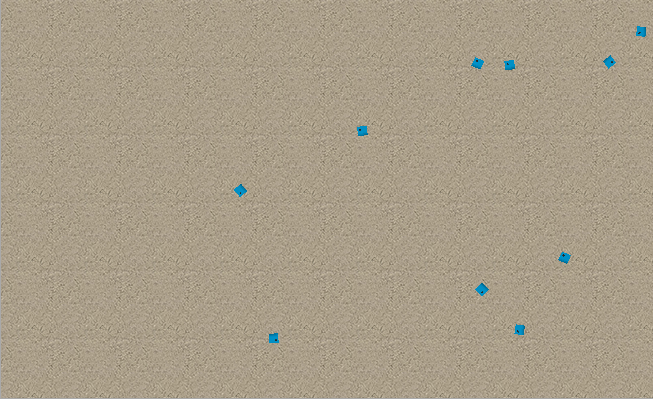
Finally, we may run the model. The buildings will be located within the area defined by the polygonal node
Well done, we have completed the first phase of the Air defense system tutorial. Proceed to Phase 2.
Demo model: Air Defense System — Phase 1 Open the model page in AnyLogic Cloud. There you can run the model or download it (by clicking Model source files).-
How can we improve this article?
-