

The Palette view provides the list of graphical model elements grouped by categories in a number of stencils (palettes).
To show or hide the Palette view
- Choose View >
 Palette
from the main menu.
Palette
from the main menu.
By default, the Palette view is docked to the left side of the window.
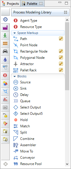 The Palette view
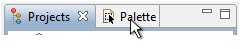
The Palette view shares the same area within the application window with the Projects view. If Projects or some other view (e.g. Search) is shown there, just click the Palette view tab to bring it on top:
The Palette view is the place where you can find any AnyLogic graphical element and add it onto a graphical diagram of some agent class or experiment.
To add an element onto a diagram of agent type or experiment
- Drag the element from the Palette view to the place of the diagram, where you want to place this element.
Some elements (marked in the Palette with  icons) also support drawing mode — the alternative way of adding these elements onto the diagram in addition to common drag’n’dropping (please refer to the Adding palette elements to the diagram section for more information).
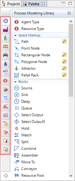
The Palette view consists of a number of default palettes and may also display palettes of third-party AnyLogic libraries plugged-in by user.
To show a particular palette
-
Hover the mouse over the vertical navigation bar docked to the left side of the Palette click the icon of the required palette.
-
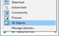
Wait for the popup window with the palette names to appear:
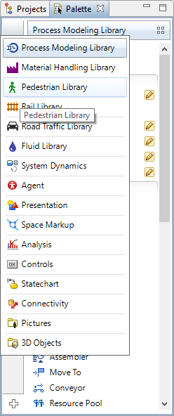
- Then just select the required palette by clicking the corresponding name in the list.
You can close any rarely used palette (or library palette as well) whenever you need and reopen any earlier closed palettes.
To open or close a palette
-
Click on the
 Palettes... button in the bottom of the Palette view.
- This will open the list of currently available palettes and library stencils.
- Select the required item from this list. The corresponding palette will be opened and made currently selected in the Palette view.
You draw model elements in the graphical editor by simply dragging them from the corresponding page of the Palette view.
To add an element onto a diagram of agent or experiment
- Drag the element from the Palette view to the place of the diagram, where you want to place this element.
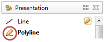
The pencil icon  drawn near a palette element means that this element supports drawing mode. Drawing mode is the additional way of adding elements onto the diagram in addition to common dragging.
When you drag an element onto the diagram, you always get the shape of the predefined size and form. But sometimes you may want to draw a shape of the required form at once. In this case you should use the drawing mode.
To activate the drawing mode, double-click the element in the Palette. The element icon should turn to :
Now you can draw a shape in the graphical editor using some common set of actions. However, these actions slightly differ for different elements:
-
State, Rectangle, Rounded Rectangle, Oval, Line
Drag to the graphical editor where you want to draw the shape. Stop dragging when you’ve got the shape of the required form and size. -
Connector, Transition, Polyline, Curve
Successively draw points of a shape by clicking at the required points on the diagram. Double-click to place the end point and finish.
Let’s illustrate the difference between two ways by the example of a rectangle.
To draw a rectangle of the predefined form
-
Drag the Rectangle
 element from the Presentation palette to the graphical editor (right to the place where you want to locate this shape).
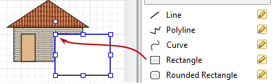
- Now you can modify the appearance of the drawn rectangle by dragging its handles to required points on the presentation.
Sometimes it would be more convenient to use drawing mode.
To draw a rectangle of the required form at once
-
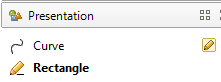
Double-click the Rectangle element in the Presentation palette.
This activates the drawing mode for this element (its icon turns into to indicate that the drawing mode is currently turned on).
- Press the left mouse button in the graphical editor where the upper left corner of the rectangle should be placed.
-
Hold the mouse button pressed; drag the cursor to the point where you want to place the lower right corner of the rectangle.
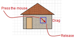
- Release the mouse button.
-
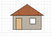
As the result, a rectangle of the required form will be drawn at once.
To simplify working with the Palette view, AnyLogic allows users to customize its appearance. The settings are saved and applied again on next AnyLogic launches.
You can customize the way palette elements are displayed in the Palette. By default they appear as small icons. If needed, you can show them as a list (if there are too many elements in the palette), or as large icons (if small icons are hardly distinguishable).
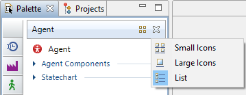
To change the appearance of the palette elements
-
Hover the mouse over the title bar of the required palette. Click the button
 and choose the appearance type from the popup menu: Small Icons, Large Icons, or List:
| List | Small icons | Large icons |
|---|---|---|
 |
 |
 |
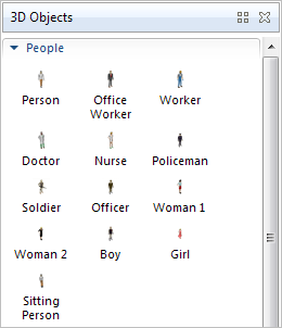
- Small Icons — In this mode elements are displayed as small icons that are arranged throughout the palette.
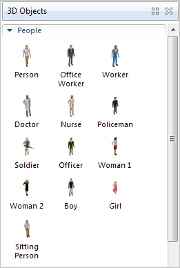
- Large Icons — In this mode elements are displayed as large icons that are arranged throughout the palette. This mode is mostly used when the user chooses elements by their icons, not by their names, and wants icons to be clearly distinguishable.
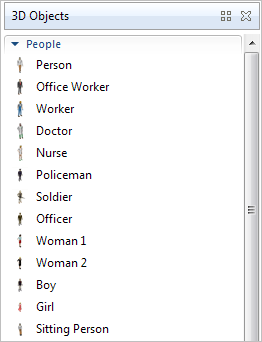
- List — In this mode elements are displayed in one vertical column. This mode may be useful when elements have too long names that do not fit in the allotted space in other modes; and also when the Palette view is vertically oriented — in this case this mode provides the most effective way of arranging the elements in the palette space.
Element appearance settings are defined individually for each palette. Therefore you can use various modes for different palettes, e.g. use Large Icons mode in Pictures and 3D Objects palettes, and List mode in all other palettes.
AnyLogic provides a convenient mechanism of searching elements in the palettes. It may be needed when you cannot find the required element in the palette, or do not remember what particular palette contains it.
To find the palette element
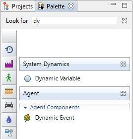
- Click in the Palette view.
-
Start typing the element name You will see that the view contents are filtered: only the elements with the names that start with the specified string are shown in the view now.
-
Having found the required element, add it onto the graphical diagram and close the search bar by clicking the button
 to the right of the Look for string:
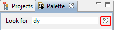
- This will bring the Palette view to its normal state.
If the element name consists of several words, you may start typing any of them (as in the given example — you may type function to find the Table function). This can be convenient for example when you are searching for Pedestrian Library objects: since names of all objects of this library start from Ped, you may directly type the second, meaningful, word, e.g. you can type just GoTo to find PedGoTo.
Starting with version 8.9.4, users can add preferred elements to the new palette named  Favorite.
The palette contains two sections. The top section is controlled by you: you can manually add your preferred elements here. The second section, named Last used, contains up to ten most recently used elements.

You can add your favorite elements from any palette to the Favorite palette to access them quickly.
To add the element to favorites
- Right-click (macOS: Ctrl + click) the item in the palette and choose Add to favorite from the popup menu.

The added element will appear in the
Favorite palette.
To remove the element from favorites
Right-click (macOS: Ctrl + click) the item in the
Favorite palette or in its original palette and choose Remove from favorite from the popup menu.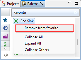
-
How can we improve this article?
-