

Network port enables the movement of transporters between separate standard Process Modeling Library networks or the movement of material items between separate Material Handling Library conveyor networks that have no physical connection. Pedestrians cannot move via network ports. The connection can only be established between networks of the same type: either both of them must be conveyor networks or both must be standard networks.
One network port can only be connected to one network path or conveyor.
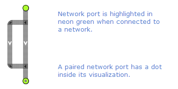
Network ports always operate in pairs. To create a pair of connected ports, you have to specify one of them in the other port’s parameters. The paired ports can exist either on the same level or on different levels in the model hierarchy.
Network ports can be utilized to establish connection between:
- Levels of multi-tier network.
- Reusable network sections and the main network.
To create a pair of network ports
- Drag the
 Network port element from the Space Markup section of the
  Material Handling Library palette to the intended agent diagram and place it at any desired location of the network in the graphical editor.
 - Repeat step 1 to add the second network port.
- Select the port you want to pair and go to the port’s Pair with port parameter in Properties view.
- If the network ports you want to connect are located on the graphical diagram of one agent, open the drop-down list and select the name of the intended port. You can also click the button located to the right of the drop-down list: all elements in the graphical editor will be muted except for the network ports available for pairing. Click the intended network port in the graphical editor to select it.
-
If the network ports are located on the graphical diagrams of different agents, switch the field to dynamic value editor and type in the corresponding <agent name>.<network port name>.
You do not have to specify the paired element for both ports in the pair, doing it for one of them is enough to establish the connection.
After you have specified the connection in the network port’s properties, a dot appears in the middle of this port’s visualization in the graphical editor.
To create network ports and paired network ports programmatically, use the corresponding functions of conveyors and paths.
- General
-
Name — The name of the network port. The name is used to identify and access the port from code.
Ignore — If selected, the network port is excluded from the model.
Visible on upper agent — If selected, the network port is visible on the upper agent where this agent lives.
Lock — If selected, the network port’s shape is locked. Locked shapes do not react to mouse clicks — it is impossible to select them in the graphical editor until you unlock them. It is frequently needed when you want to prevent editing this shape while drawing other shapes over it.
Pair with port — Here you specify which network port you want to connect to.
Level — Level to which this network port belongs.
You can dynamically modify the properties of the element at model runtime using the following API.
- Network and network elements
-
Function Description INetwork<?, ?> getNetwork() Returns the network this network port belongs to. - Paired port
-
Function Description NetworkPort getPairedPort() Returns the paired port for this network port.
-
How can we improve this article?
-