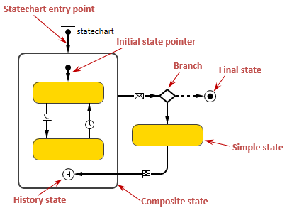
While using events is quite clear, sometimes you may need to define some more sophisticated behavior that cannot be defined using events and dynamic events. This can be done using statecharts. Statechart is the most advanced construct to describe event- and time-driven behavior. For some objects, this event- and time-ordering of operations is so pervasive that you can best characterize the behavior of such objects in terms of a state transition diagram – a statechart.
Statechart has states and transitions. Transitions may be triggered by user-defined conditions (timeouts or rates, messages received by the statechart, and Boolean conditions). Transition execution may lead to a state change where a new set of transitions becomes active. States in the statechart may be hierarchical, i.e. contain other states and transitions.
Statechart is used to show the state space of a given algorithm, the events that cause a transition from one state to another, and the actions that result from state change.
By using statecharts you can visually capture a wide variety of discrete behaviors, much more rich than just idle/busy, open/closed, or up/down status offered by most block-based tools.
Demo model: Statechart for Generic Resource Open the model page in AnyLogic Cloud. There you can run the model or download it (by clicking Model source files). Demo model: Statechart for Generic ResourceOpen the model in your AnyLogic desktop installation.The behavior of a statechart is defined in a graphical editor using the following statechart constructs:
Statechart elements are added on the diagram from the Statechart stencil of the Palette view.

-
How can we improve this article?
-


