

In AnyLogic the whole agent structure is defined on one presentation diagram that is drawn in the graphical editor. This feature enables users to see all elements of an agent, including animation, charts, statecharts, etc. in the same window at model runtime. And thus the user can analyze the whole state and behavior of the model at a glance. However, in case of large and complex models agents commonly contain a great number of elements, which may result in another inconvenience: it could be impossible to fit all these elements within the model frame that defines the presentation area shown at runtime.
AnyLogic offers a special element for solving this problem — view area. Using this element, you can mark out some particular areas on the presentation diagram, containing some logically detached groups of elements or parts of the diagram. Once you have defined such view areas, you can easily switch between them at the model runtime using special navigation tools. This feature enables users to quickly navigate to some particular places of agent’s diagram.
- For example, you can place agent animation or charts visualizing model’s statistics in one area, and then place stock-and-flow diagram or a flowchart combined from Process Modeling Library blocks in the other one.
- Or, suppose, you model a factory and the layout of factory shops is large enough to fit in the model window. In this case you can define several separate view areas (one for each factory shop) and switch between these areas at the model runtime, examining how different shops operate by turns.
To define a view area
- Drag the
 View area element from the
  Presentation palette to the graphical editor.
 -
You’ll see the view area’s anchor
 and the orange rectangle appeared in the graphical editor. This anchor marks the view area’s top-left corner. The orange rectangle marks the actual area that will be displayed when switching to this view area in the model design mode or at model runtime:
- By default, the size of a newly added view area matches the model frame size. To change the size, select the view area’s anchor in the graphical editor and drag the handles at its borders. Alternatively, set the position and size of the view area in the Position and size section of its properties.
- General
-
Name — The name of the area. It is used to identify and access the element from code.
Show name — If selected, the area’s name is displayed on a presentation diagram.
Ignore — If selected, the view area is excluded from the model.
Title — Here you can define a title for this view area. The title will be shown in navigation lists opened by toolbar buttons (View areas at the model design time and Show area... at the model runtime correspondingly).
- Position and size
-
X — The x-coordinate of the area’s anchor.
Y — The y-coordinate of the area’s anchor.
Width — The width of the area (in pixels).
Height — The height of the area (in pixels).
View areas are used either for navigation through the graphical editor in the model design mode and for navigation through the presentation window in the model execution mode. Navigating to a view area will automatically scale the view area's content to fit the model frame as closely as possible. For example, if the view area size is smaller than the model frame size, navigating to this view area will scale up the corresponding part of the presentation.
To navigate to a view area in the model design mode
- Click the agent diagram to make the graphical editor active.
-
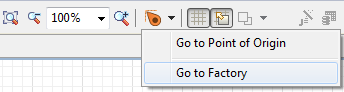
Click the View areas toolbar button and choose from the drop-down list the particular view area you want to navigate to.
To navigate to a view area in the model execution mode
Navigating between view areas in the model execution mode is only possible when the model is already running. If you have previously disabled the autorun option Skip experiment screen and run the model in the properties of the Simulation experiment, then click the Run  button and follow the steps below to navigate between view areas:
-
Open developer panel by clicking the
 icon in the bottom right corner of the model window.
- In the developer panel go to the agent navigation section
 and click the select view area to navigate drop-down menu control.
 - Select the view area that you want to see from the drop-down menu and it will appear in the model window.
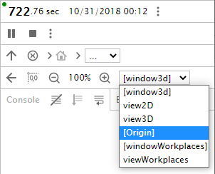
There are two types of view areas that are only accessible from the developer panel in the model execution mode.
The first one is called [Origin]. This is a view area that every agent has by default. It corresponds to the presentation area defined by the model frame.
The second is the view area that appears if the agent has a 3D window added to its presentation, and this 3D window has Create view area at runtime option enabled in its Advanced properties. By default, its name is [window3d], but if you change the name of the 3D window, the corresponding view area will be accessible from the developer panel’s view area control by this new name in square brackets.
You can place on presentation your own elements that will navigate to some view area on mouse click. To implement this, you should write the following code in the corresponding property of that element (Action in the case of a control or On click in the case of a presentation shape):
areaName.navigateTo();
To switch to the default view area [Origin], use the following code:
_origin_VA.navigateTo();
To navigate to the 3D window view area, use _window3d_VA.navigateTo();
If you want to switch to a specific view area automatically on model start, then you should place the code in the On startup action of the
![]() Mainagent. For example, to show the contents of view3d 3D window defined on the
Mainagent. For example, to show the contents of view3d 3D window defined on the
![]() Mainagent diagram, use the following code in the On startup action field:
Mainagent diagram, use the following code in the On startup action field:
_view3d_VA.navigateTo();
View areas can be used not only to switch between parts of a single agent, but also between different agents. Consider the top-level agent
![]() Mainwith a population people[..]. To access the 124-th agent's view area from
Mainwith a population people[..]. To access the 124-th agent's view area from
![]() Main, write:
Main, write:
people(123).areaName.navigateTo();
where areaName is the name of the view area of the
![]() Person agent that you want to access
Person agent that you want to access
and vice versa, to go one level up from an embedded agent to its container (
![]() Mainagent), you can call the code:
Mainagent), you can call the code:
main.areaName.navigateTo();
where areaName is the name of the view area of the
![]() Mainagent that you want to access
Mainagent that you want to access
- Navigating to a view area
-
Function Description void navigateTo() Navigates to the view area. - View area location
-
Function Description double getX() Returns the X coordinate of the view area. double getY() Returns the Y coordinate of the view area. void setX(double x) Sets the X coordinate of the view area.
x — the new value of X coordinate.void setY(double y) Sets the Y coordinate of the view area.
y — the new value of Y coordinate. - View area size
-
Function Description double getHeight() Returns the height of the view area. double getWidth() Returns the width of the view area. void setHeight(double height) Sets the height of the view area.
height — new height of the view area.void setWidth(double width) Sets the width of the view area.
width — new width of the view area. - View area title
-
Function Description String getTitle() Returns the title of view area (it is shown in the navigation lists (View areas at model design time and Show area... at model runtime). void setTitle(String title) Sets the title for the view area (it is shown in the navigation lists (View areas at model design time and Show area... at model runtime).
title — the title to set.
-
How can we improve this article?
-