

Our model will simulate how the cars are taken to a track, sometimes called a lead or a drill. From there the cars are sent through a series of switches, called a ladder, onto the classification tracks.
We want to start with the rail network of this topology:
Create a new model. Name it Hump Yard and set minutes as the model time units.
Start defining the rail topology. First, draw the railway tracks.
Start with a linear track.
Draw a linear railway track
- Double-click the
 Railway Track element in the
 Rail Library palette.
 - In the
 Main diagram, click to start drawing the track.
 - Finish drawing a track with a double-click where you want to place the end point of the track.
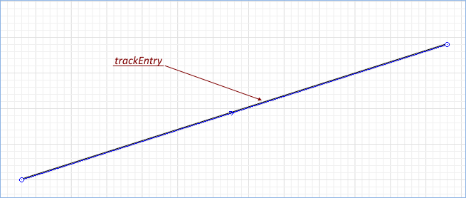
Name this track trackEntry since trains will appear on this track. We will give meaningful names only to the tracks that will be referred to by the flowchart blocks. Other tracks may have their default names.
If it is the first track in the model that you are drawing, you will see a message prompting you to change the model scale to: 2.0 pixels per 1 meter. We recommend you to follow this advice as the offered scale is frequently used in typical railroad traffic models.
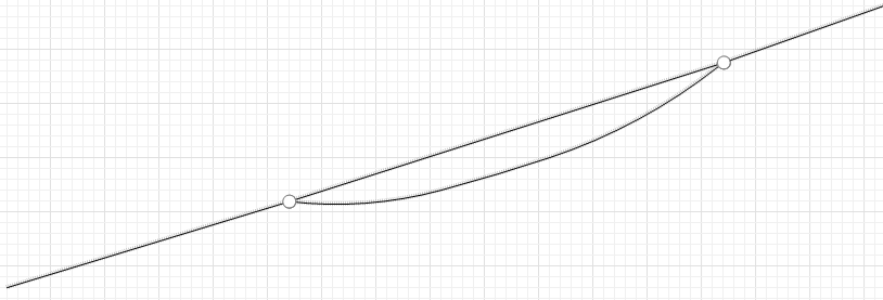
Finally you will see the drawn linear track that will be used by our train. Now let’s draw the by-pass track that will be used by the locomotive to approach the train from behind to further move it to the hump yard. This track will be of curved shape and its drawing scenario will differ from what you have previously followed.
Draw a curved by-pass track
- Double-click the
Railway Track element in the
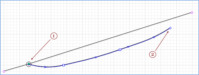
Rail Library palette. Then click on point on the existing track to start drawing the by-pass track. The circle denoting a switch will appear automatically.
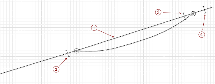
- Draw more track segments to get the track shape as shown on the figure below. To append a curved segment, press the left mouse button at the point where the curved segment ends and then move the mouse with the button being pressed. While dragging the mouse you will see how the curving radius changes. When done, release the mouse button. Finish drawing the track with a double-click. You cannot put the end point on the same track where you started drawing (
 trackEntry), so double-click near trackEntry (see below, point 2).
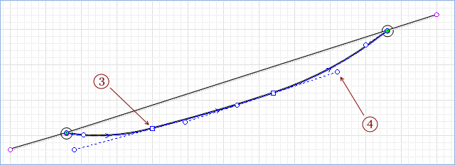
- Drag the track end point onto the trackEntry to create a switch.
Adjust curved railway track
- Select the track you need to edit by clicking on it.
- Right-click on the selected track and choose Edit Using Guiding Lines from the drop-down menu.
- Move a rectangle handle to move the segment end point.
- Move a circle handle on the end of the dashed guiding line to change the curving radius.
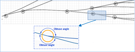
- Railway network consists of tracks and switches. Railway switches appear automatically in the shape of a circle when you connect a branch track to the existing railway track. You cannot connect more branch tracks to the same point.
- At each switch there must be at least two obtuse angles out of three between the track ends. The switch determines the routes based on those angles.
Modify the rail yard
The lead track will be divided into tracks each time we create railway switches on it. In our case we created two switches by connecting a by-pass track in two points of the existing track. As a result the lead track is divided into three tracks with their own names and properties.
Now we will give a meaningful name to the track between the switches and add Position on track shapes to our rail yard.
- Name this track trackArrival as it denotes the track where the train arrives to.
- Drag the
 Position On Track element from the Rail Library palette and place it as shown on picture below. Name it stopLineEntry. It will define the place where trains appear.
 - Add
Position On Track: stopLineArrival. The train will stop to detach the locomotive at this point, allowing the loco to proceed on its own.
- Add
Position On Track: stopLineHump. Rail cars will be sorted per type here.
Position on track is a space markup shape that is used to define the exact position on the railway track. This is needed when you define:
- The position on the track where the train appears.
- The position where the train should stop.
In this phase of the Hump Yard tutorial we have created a rail yard.
-
How can we improve this article?
-