

The batteries filled with acid must be delivered to the area where they will undergo the charging process. We will model the delivery with the help of the crane element and path-guided transporters.
Transporters with path-guided navigation conduct their movement along paths and nodes, which make up a network. They avoid collisions and give way at crossroads. By default, transporters select the shortest route to the destination, but you can also specify a custom route or exclude specific paths and nodes. If a collision takes place, transporters will wait for a specified period of time before resuming movement. All these options can be customized with the help of the TransporterControl block.
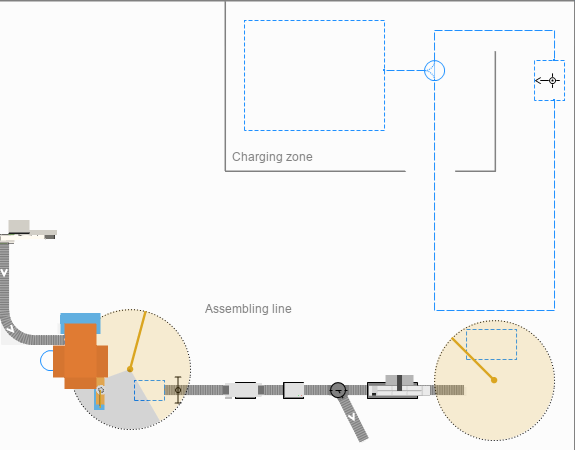
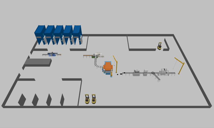
Prepare the layout
- Double-click the
 Rectangular Node element in the in the
 Space Markup palette to switch it to the drawing mode and draw the batteries charging area according to the layout.
 -
Name the node store.
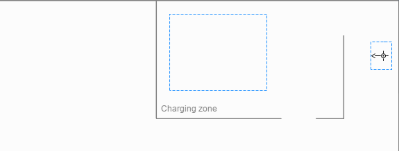
Since we are going to use the path-guided forklifts, we need to draw the network that will define the movement paths.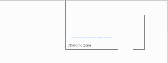
- Drag another
Rectangular Node to the
 Main graphical diagram and resize it as displayed in the image below.
 - Name the node agvHomeLocation.
-
Create one attractor in the node.
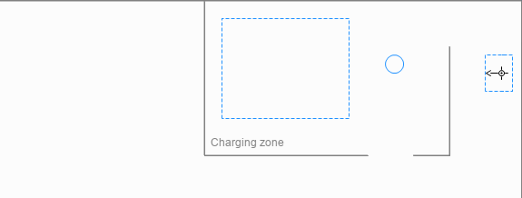
-
Drag the
 Point Node to the
Main graphical diagram, place it according to the layout.
Point Node to the
Main graphical diagram, place it according to the layout.
-
Name the node agvUnloadingPoint.
- Double-click the
 Path element in the palette to activate its drawing mode.
 - Draw the path leading from the agvUnloadingPoint to the store.
-
In the same manner draw two paths connecting the agvUnloadingPoint and the
agvHomeLocation nodes. Pay attention to the direction of each path.
If you have successfully connected the nodes, the path’s connecting points will display cyan highlights when you select the path in the graphical editor.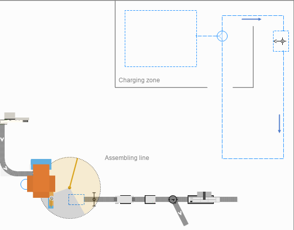
- Add an area where the forklifts will receive the batteries for transportation by drawing yet another
Rectangular Node according to the layout.
-
Name the node agvLoadingArea.

- Hold Ctrl key and click to select all nodes and paths.
- In the Multiple selection properties view, specify Show in: 2D only.
- Add a crane that will move the batteries from the conveyor to the forklift’s loading area.
-
Name it batteryCrane.
-
In the crane’s properties specify the following:
- Material item type:
Battery
- Crane height: 4 meter
- Material item type:
- Make sure that the crane’s working area fully covers the
agvLoadingArea.
Now, let’s create the logic behind this phase.
Add the logic
- Add the
 MoveByCrane block to the flowchart after the conveyBattery block.
 -
Name it toLoadingArea.
This block will control the movement of batteries by the crane.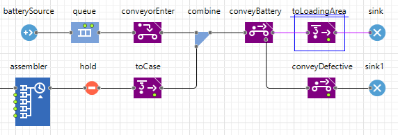
-
In the block’s properties specify the following:
- Crane:
 batteryCrane
 - Node:
agvLoadingArea
- Loading time: 5 seconds
- Unloading time: 5 seconds
- Crane:
- Next, drag the
 TransporterFleet block from the
 Material Handling Library to the
Main graphical diagram.
Material Handling Library to the
Main graphical diagram. -
Name it AGVs.
This block will define the forklift moving in the network we’ve created.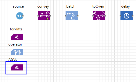
-
In the block’s properties specify the following:
- Capacity: 1
- Home locations:
agvHomeLocation
- New transporter:
Forklift
- Add the
 MoveByTransporter block to the flowchart after the toLoadingArea block.
 -
Name it toChargingArea.
This block will control the movement of a forklift which will transfer the batteries from the production line to the charging area represented by the store node.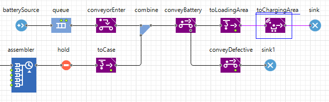
-
In the block’s properties specify the following:
- Node:
store
- Fleet: AGVs
- Loading time: 5 seconds
- Unloading time: 5 seconds
- Node:
-
Run the model and observe the process of battery production from start to finish.
-
How can we improve this article?
-