

At this stage of the production, the electrode groups that we have learned to model previously, are placed in a plastic battery case, which then will be filled with acid. The exact number of groups inside the case depends on the battery’s intended capacity. We will now model the assembly of electrode groups into the battery case with the help of an industrial crane.
First, we will create a new material agent type to represent the battery.
Add a new material item type
- Drag the
 Material Item Type element from the
 Material Handling Library palette to the
Main graphical diagram.
Material Handling Library palette to the
Main graphical diagram. - In the New agent wizard specify the Agent type name: Battery and click Next.
- Expand the Warehouses and Container Terminals section and select the Industrial Container 1 figure. Click Finish.
- In the
Battery graphical editor select the scale element and set the Ruler length corresponds to: 1 meter.
-
In the Dimensions and movement section of the
Battery agent type specify the following properties:
- Length: 0.3 meter
- Width: 0.2 meter
- Height: 0.15 meter
- To adjust the 3D animation so that it fits the specified dimensions of our agent type, select the 3D figure in the graphical editor and in its properties set the Additional scale to 50%.
- In the Colors section of the 3D figure’s properties specify My color: black.
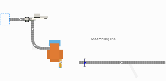
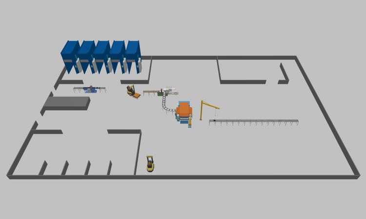
Next, let’s add the layout for this section of the production line: a conveyor, where the electrode groups are put into the battery cases, and the crane that carries the groups over from the buffer zone.
Prepare the layout
- Double-click the
 Conveyor element in the
 Space Markup palette.
 - Draw the conveyor over the layout as displayed in the image below.
- Name it batteryConveyor.

- Specify its properties as follows:
- Material item type:
Battery
- Maximum speed: 0.5 meters per second
- Initial speed: 0.5 meters per second
- Z: 20
- Width: 0.5 meters
- Material item type:
- Drag the
 Position on Conveyor element from the Material Handling section of the
Space Markup palette to the
Main graphical diagram and place it on the
batteryConveyor.
Position on Conveyor element from the Material Handling section of the
Space Markup palette to the
Main graphical diagram and place it on the
batteryConveyor.
- Name the element blockInputPosition. We will use this element to mark the exact point on the conveyor where the electrode groups must be placed inside the battery case.
- Drag the
 Rectangular Node element from the
Space Markup palette to the
Main graphical diagram and place it at the starting point of the
batteryConveyor.
Rectangular Node element from the
Space Markup palette to the
Main graphical diagram and place it at the starting point of the
batteryConveyor. - Name the node caseBuffer.
- In the node’s properties specify:
- Visible: no
- Locations layout: Arranged
- Drag the
 Jib Crane element from the Material Handling section of the
Space Markup palette to the
Main graphical diagram and place it according to the layout.
Jib Crane element from the Material Handling section of the
Space Markup palette to the
Main graphical diagram and place it according to the layout. - Name the crane batteryBlockCrane.
-
Specify the crane’s properties as follows:
- Material item type:
BatteryBlock
- In the Position and size section, specify Jib length: 3 meter and Crane height: 4 meter.
- Material item type:
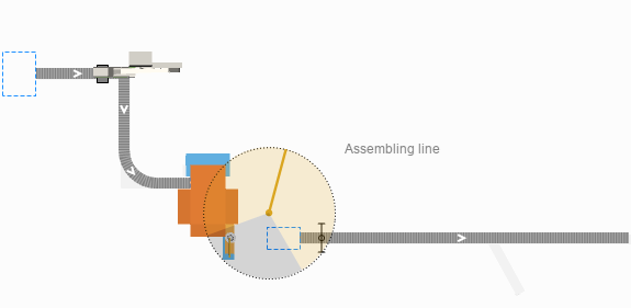
- Make sure that the crane’s working area fully covers the
assembledBlocksBuffer node and the blockInputPosition element on the
batteryConveyor. Drag the handle located at the end of the crane’s jib to increase and decrease the crane’s working area.
-
Select the Blocked zone check box and adjust its angle by dragging the handles until the blocked zone looks as displayed in the image below:
Now let’s define the logic behind this production step.
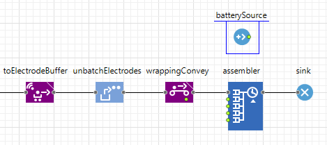
Add the battery assembly logic to the flowchart
- Drag the
 Source element from the
 Process Modeling Library palette to the
Main graphical diagram and place it above the assembler block. Make sure that these two blocks don’t connect.
Process Modeling Library palette to the
Main graphical diagram and place it above the assembler block. Make sure that these two blocks don’t connect. -
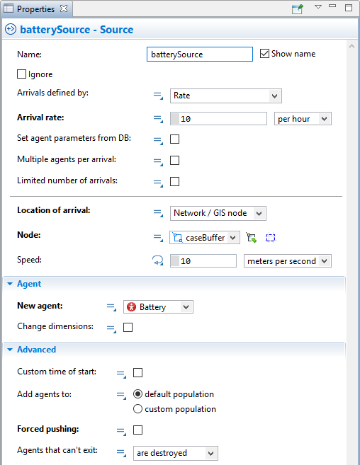
Name the source block batterySource.
This block will serve to generate agents of the Battery type.
-
Specify the following in the batterySource properties:
- Arrivals defined by: Rate
- Arrival rate: 10 per hour
- Location of arrival: Network/GIS node
- Node:
caseBuffer
- New agent:
Battery
-
Deselect the Forced pushing check box.
-
Drag the
 Queue block from the
Process Modeling Library palette to the
Main diagram and place it after the batterySource block. Make sure the connection between these two blocks is established properly.
Queue block from the
Process Modeling Library palette to the
Main diagram and place it after the batterySource block. Make sure the connection between these two blocks is established properly.
We use this block to model the battery cases waiting to be used in the buffer zone.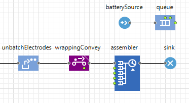
-
In the queue block’s properties, specify:
- Capacity: 25
- Agent location:
caseBuffer
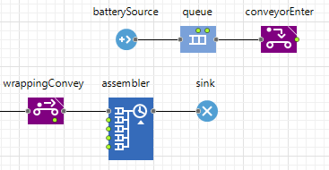
- To model the movement of battery cases from the buffer zone to the assembly conveyor, drag the
 ConveyorEnter block from the
Material Handling Library palette to the
Main diagram and place it after the queue block.
ConveyorEnter block from the
Material Handling Library palette to the
Main diagram and place it after the queue block.
-
In the conveyorEnter properties, specify:
- Entry point defined as: Position on conveyor
- Position on conveyor: blockInputPosition
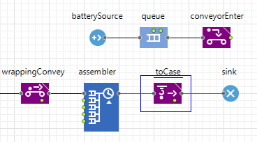
- To model the transfer of the electrode groups from the buffer zone to the battery case, drag the
 MoveByCrane block from the
Material Handling Library palette to the
Main diagram and place it after the assembler block.
MoveByCrane block from the
Material Handling Library palette to the
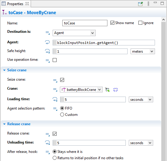
Main diagram and place it after the assembler block. - Name the block toCase.
-
In the toCase block’s properties, specify the following parameters:
- Crane: batteryBlockCrane
- Destination is: Agent
- Loading time: 5 seconds
- Unloading time: 5 seconds
- Crane:
-
Switch the Agent parameter to dynamic mode and type the following line of code: blockInputPosition.getAgent().
This function returns the agent that is currently located at the blockInputPosition point.
Now, that we have finished defining the logic behind the generation and transfer of the battery boxes to the intended place, we need to connect the two processes into a single flowchart.
- Delete the connector between the toCase block and the sink block.
- Drag the
 Combine block from the
Process Modeling Library palette to the
Main diagram and place it after the conveyorEnter block. Make sure the connection is established via the combine block’s upper port.
Combine block from the
Process Modeling Library palette to the
Main diagram and place it after the conveyorEnter block. Make sure the connection is established via the combine block’s upper port. -
Double-click the out port of the toCase block and drag the connector to the combine block’s lower in port. Release the mouse button when the connection point is highlighted in cyan.
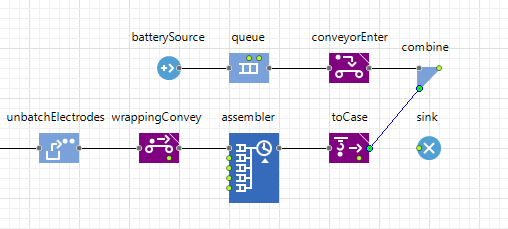
- In the combine block’s properties specify The resulting agent is: agent 1.
- Place the sink block after the combine block and make sure they are connected.
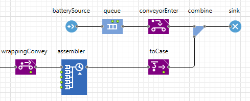
- Run the model.
Inevitably, an error will occur when the crane attempts to transfer electrode groups to an absent battery case. We can solve this problem with the help of the Process Modeling Library.
Synchronize the group assembly process and the battery case preparation
-
Drag the
 Hold block from the
Process Modeling Library palette and place it in the flowchart between the assembler block and the toCase block.
Hold block from the
Process Modeling Library palette and place it in the flowchart between the assembler block and the toCase block.
This block will help us control the flow of electrode groups: we will stop the flow until a new battery case becomes available.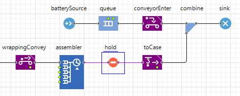
-
In the block’s properties specify the Mode: Block automatically after N agents (use unblock()) and select the Initially blocked check box.
Now, we need to make sure that the unblock() function is called at the appropriate moment of time to synchronize the two production flows. -
Expand the Actions section of the conveyorEnter block and type in the following line of code in the On enter field: hold.unblock().
Now the hold block’s unblock() function will be called every time when a battery case enters the conveyor where the crane must place electrode groups inside it. For the rest of the time the movement of electrode groups will be blocked. -
Run the model again and observe the production process.
-
How can we improve this article?
-