

 Attractors inside a node
An Attractor allows you to control the position of an agent location inside a rectangular or a polygonal node.
- If the node defines the destination of the agent’s movement (for example, is referenced by MoveTo), attractors define exact positions inside the node.
-
You can set a specific attractor as the destination. The following blocks allow you to define a destination or location with an attractor:
- Source, Split, Assembler, Batch, Enter, TransporterFleet — location of the agent.
- MoveTo, ResourceSendTo, Seize, Service, MoveByTransporter, SeizeTransporter, MoveByCrane, RackPick — destination for agents or moving resources.
- If the node defines the waiting location (is referenced by Delay or Queue), attractors define exact points where agents will wait within the node. Agents will go to the attractor location to wait.
- You can send agents to the attractor by calling one of the moveTo() agent movement functions.
In pedestrian simulation, Attractor allow you to control the location of pedestrians within a node.
- If the node defines the destination of the pedestrian movement (is referenced by PedGoTo), attractors define the exact destination points inside the node.
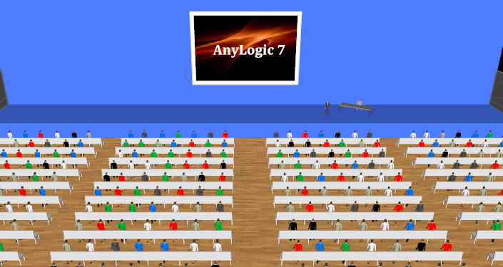
- If the node defines the pedestrians waiting location (is referenced by PedWait), attractors define the exact points where pedestrians will wait inside the node. Pedestrians will go to the attractor location to wait. This option may be used to simulate information boards, display shelves in stores, and so on.
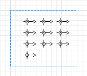
 Waiting positions (seats) defined with attractors
To draw an attractor inside the node
-
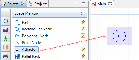
Drag the
 Attractor element from the
  Space Markup palette into the node.
To draw several attractors
-
Double-click Attractor in the
 Space Markup palette. Its icon will turn into
  . Now you can add attractors by clicking inside of nodes.
-
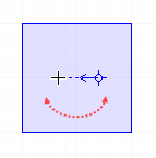
You add one attractor each time you click inside the node. All new attractors have the default orientation as shown in the figure above. However, you can change attractor’s orientation while drawing it: do not release the mouse button after
the click, but move it around until you get the orientation you need.
- To exit the drawing mode, click some area in the graphical editor outside the node.
-
After you finish drawing, all added attractors will be selected with their properties open. You may find this useful for defining orientation for several attractors at once:
To add several attractors using the wizard
- Click the node in the graphical diagram.
- In the node properties, click Attractors... button. You will see Attractors dialog box.
-
In the dialog, specify how many attractors you want to create. You may do this by explicitly specifying the Number of attractors, or filling the whole node with attractors, preserving the specified Space between attractors, or
placing them in a Grid with cells of specified width and height.
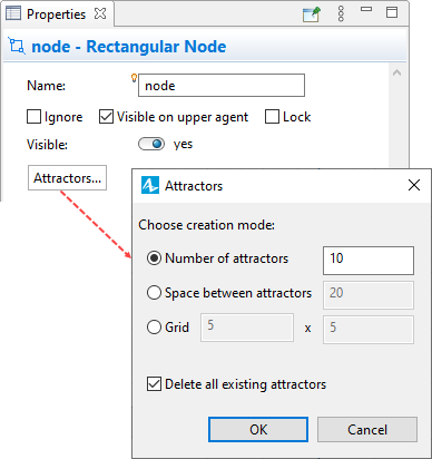
- If you need to restructure attractors, select the option Delete all existing attractors and also define creation mode before you click OK. If you wish to clear all attractors from the node without creating new ones there, select this option and specify 0 in creation mode Number of attractors, then click OK.
When you add attractors (either manually or using the wizard), their creation order also defines the sequence of the agents' movement destinations. You can verify the creation order by looking at the names of the attractors (attractor1, attractor2, …). Agents will select attractors one by one according to this order. In case you need to change the order, you should change the positions of the corresponding attractors but not their names.
The arrow of the attractor defines the orientation for agents inside an attractor. This is generally important if you have 2D or 3D animation and want the agent animation shapes to face the exact direction (for example, you may want the customer to face the ATM).
See the use of attractor’s orientation in the process-oriented tutorial:
Tutorials > Bank Office > Phase 3. Adding tellers > Set up space markup for the tellers > Step 5. We will use attractors to define the tellers.
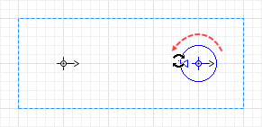
You can change the Orientation in the properties of the attractor, or visually define the angle by dragging the arrow’s endpoint in the graphical editor:
You can add attractors one by one; however, if the attractors form a regular structure, it makes sense to add several attractors at once using the special wizard.
- General
-
Name — The name of the attractor. The name is used to identify and access the attractor from code.
Ignore — If selected, the attractor is excluded from the model.
Visible on upper agent — If selected, the attractor is visible on the upper agent where this agent lives.
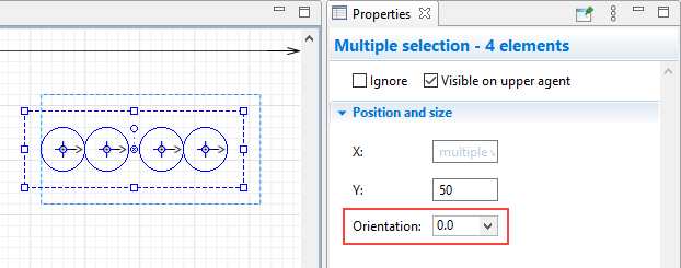
- Position and size
-
X — the absolute X-coordinate of the attractor.
Y — the absolute Y-coordinate of the attractor.
Orientation — Defines where agents should be oriented when they reach the attractor and wait there (measured clockwise, in degrees).
You can dynamically modify shape properties at model runtime using the API.
- Position
-
Function Description double getX()
double getY()
double getZ()Returns the X (Y, Z) absolute coordinate of the attractor.
The Z coordinate is defined by the corresponding coordinate of the node. - Orientation
-
Function Description double getOrientation() Returns the attractor’s orientation in radians (in the clockwise direction).
-
How can we improve this article?
-