

Level gate enables the movement of transporters with free space navigation between different levels. Pedestrians cannot move via level gates.
Level gates always operate in pairs. To create a pair of connected level gates, you have to specify one of them in the other gate’s properties.
Level gates are represented as lines. The length of the line is a visual marker of a passage through which transporters can move to another level. The gate length can be increased or decreased. If the paired gates have different lengths, the transporters will move within the length limit of the shorter gate. The length limit is calculated from the starting point of the level gate.
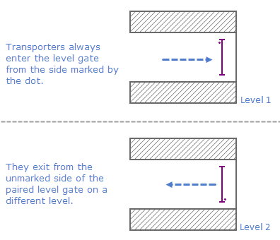
A dot on the level gate’s animation serves to distinguish the entrance side of the gate. The transporter will always enter the level gate from the side marked by the dot and exit the paired gate from the side not marked by the dot.
Demo model: Level Gate Open the model page in AnyLogic Cloud. There you can run the model or download it (by clicking Model source files). Demo model: Level GateOpen the model in your AnyLogic desktop installation.To create a pair of level gates
- Drag the
 Level Gate element from the Space Markup palette to the required level and place it at the desired location of the graphical editor.
 - Repeat step 1 to add the second level gate.
- Select the gate you want to pair and go to the gate’s Pair with gate parameter in Properties view.
- If the level gates you want to connect belong to one agent, open the drop-down list and select the name of the intended gate. You can also click the button located to the right of the drop-down list: all elements in the graphical editor will be muted except for the level gates available for pairing. Click the intended level gate in the graphical editor to select it.
-
If the level gates belong to different agents, switch the field to dynamic value editor and type in the corresponding <agent name>.<level gate name>.
You do not have to specify the paired element for both gates in the pair, doing it for one of them is enough to establish the connection.
- General
-
Name — The name of the level gate. The name is used to identify and access the gate.
Ignore — If selected, the level gate is excluded from the model.
Visible on upper agent — If selected, the level gate is visible on the upper agent where this agent lives.
Lock — If selected, the gate’s shape is locked. Locked shapes do not react to mouse clicks — it is impossible to select them in the graphical editor until you unlock them. It is frequently needed when you want to prevent editing this shape while drawing other shapes over it.
Pair with gate — Here you specify which level gate you want to connect to.
Line color — Here you can specify the color of the level gate animation.
- Position and size
-
Level — Level on which this gate is located.
X — X-coordinate of the gate’s starting point.
Y — Y-coordinate of the gate’s starting point.
dX — X-offset of the gate’s ending point in relation to the gate’s starting point.
dY — Y-offset of the gate’s ending point in relation to the gate’s starting point.
- Advanced
-
Show name — If selected, the gate’s name will be displayed in the graphical editor.
- Position
-
Function Description double getX() Returns the X-coordinate of the gate’s starting point. double getY() Returns the Y-coordinate of the gate’s starting point. double getDx() Returns the X-coordinate of the gate’s ending point. double getDy() Returns the Y-coordinate of the gate’s ending point. - Paired gate
-
Function Description MarkupPort getPairedPort() Returns the paired gate of this level gate. setPairedPort(MarkupPort pairedPort) Sets the paired gate for this level gate.
pairedPort — a level gate from a different level. - Level
-
Function Description Level getLevel() Returns the level, where this gate is located. - Points
-
Function Description boolean contains(double px, double py) Returns true if the gate contains the point with the given coordinates; returns false otherwise.
px — the X-coordinate of the point.
py — the Y-coordinate of the point.boolean contains(double px, double py, double distance) Returns true if the gate contains the point with the given coordinates using the given distance tolerance; returns false otherwise.
px — the X-coordinate of the point.
py — the Y-coordinate of the point.
distance — the distance tolerance to determine whether the given point lies within the gate proximity.boolean containsSq(double px, double py, double squareDistance) Returns true if the gate contains the point with the given coordinates using the given square distance tolerance; returns false otherwise.
px — the X-coordinate of the point.
py — the Y-coordinate of the point.
squareDistance — the square of distance tolerance to determine whether the given point lies within the gate proximity. - Visibility
-
Function Description boolean isVisible() Returns true, if the level gate is visible; returns false otherwise. void setVisible(boolean v) Sets the visibility of the level gate.
v — visibility. If v is true, the level gate is set to be visible, if it is false — the level gate is not visible. - Color
-
Function Description Color getColor() Returns the color of the level gate, or null if the level gate has no color. void setColor(Color color) Sets the color of the level gate.
color — the new color. - Removal
-
Function Description void remove() Removes the level gate from the presentation. If the gate is not a part of presentation, the function does nothing. Removal from the presentation does not necessarily mean removing from the model logic, since logical networks and routes may have been created before the removal and survive it.
-
How can we improve this article?
-