

We will create the initial ![]() Transport agent type configuration.
Transport agent type configuration.
Statechart is the most advanced construct to describe event- and time-driven behavior. For some objects, this event- and time-ordering of operations is so pervasive that you can best characterize the behavior of such objects in terms of a state transition diagram — a statechart.
Statechart has states and transitions. Transitions may be triggered by user-defined conditions (timeouts or rates, messages received by the statechart, and Boolean conditions). Transition execution may lead to a state change where a new set of transitions becomes active. States in the statechart may be hierarchical, i.e. contain other states and transitions.
Statechart is used to show the state space of a given algorithm, the events that cause a transition from one state to another, and the actions that result from state change.
Add the transport variables
- Go to the
 Projects view and double-click
 Transport agent type to open its graphical diagram.
 - Add a
 Variable from the
 Agent palette.
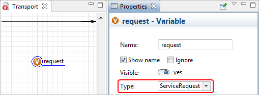
 - Name the variable request and set its type to ServiceRequest:
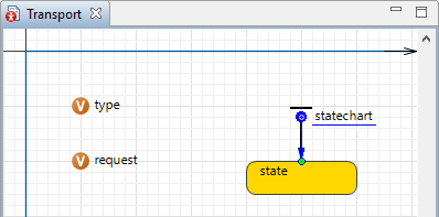
- In the same manner add another variable, name it type and set its type to TransportType.
Draw transport statechart
- We will use the
 Statechart palette elements to define the transport agent type behavior. Drag the
 Statechart Entry Point element into the graphical editor of
Transport. It defines the beginning of the whole diagram. Add a
Statechart Entry Point element into the graphical editor of
Transport. It defines the beginning of the whole diagram. Add a
 State by dragging it from the
Statechart palette and dropping the state under the statechart entry point. To add a transition, double-click
State by dragging it from the
Statechart palette and dropping the state under the statechart entry point. To add a transition, double-click
 Transition in the palette. Its icon will turn into
  , it means the tool is in the drawing mode. Now you can draw transitions by clicking in the graphical editor. Since the transitions must be connected to the states, you can click in the state when drawing to ensure proper connection. When the elements are successfully connected, AnyLogic displays a cyan-colored point in the place of connection.
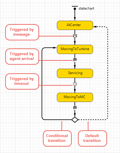
- At this phase we will only create an "empty" statechart that consists of four states, six transitions of different types and one branch.
- The states are called AtCenter, MovingToTurbine, Servicing, MovingToMC. These are basically all actions and routes of trucks and helicopters in the model. Make sure you follow the structure that is shown in the figure below. In the properties of the transition leading from the branch to the
MovingToTurbine state select Conditional option.
- The "internals" of some of these states and transitions refer to the model elements we have not yet defined. On the other hand, we need this statechart now because some of those model elements that we are going to define in further phases refer to this statechart and states in it. That is why we will finish configuring
Transport at the very end of model development process.
Next, let’s define the transport type choice according to request type and the availability of trucks and helicopters at the maintenance center.
-
How can we improve this article?
-