

Road is a graphical space markup element that represents a continuous road (i.e. the one that does not contain any intersections). Using roads, intersections, and other space markup elements you draw road networks for Road Traffic Library models.
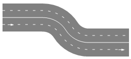
Road may contain multiple linear and/or curved segments (the road on the figure above has two linear segments and one curved segment in the middle).
Such road attributes as traffic direction (right-hand or left-hand), lane width, road surface color, etc. are configured not in the road properties, but in the properties of the road network this road belongs to. The road network is created automatically when you draw a single road and can be extended according to your modeling needs.
Road may contain arbitrary number of lanes. Road can be one-way, in this case all cars move in one direction, or two-way, in this case the road has a number of forward lanes and a number of backward lanes. The road on the figure above has two forward lanes (the arrow on the road shows the forward direction), and two backward lanes (the top ones, cars move there from right to left). Road Traffic Library does not support lanes where cars can move in both directions.
One road has a constant number of lanes throughout its whole length. To model a lane merge, connect two roads with different number of lanes.
Road can have sloped segments, you can adjust the road shape by changing the road segment ends’ Z-coordinates in the road’s Points properties section.
Road knows all cars that are (fully or partially) located on it, and you can obtain those cars using the road API.
Drawing a road
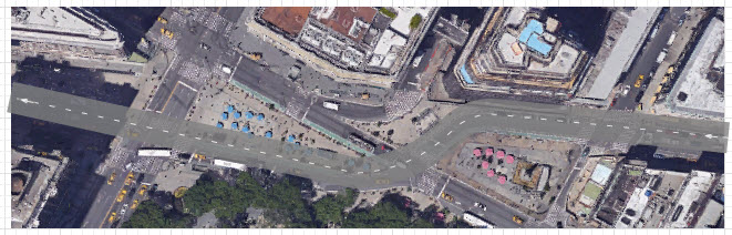
Let us demonstrate how to draw a road by the example of Broadway near Madison Square Park and the Flatiron Building:
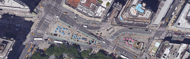
If you want to follow this short tutorial, use this image in your model (save the image to your computer by right-clicking the image above and selecting Save image as from the menu).
To draw a road
- Before you draw the road, we advise you to switch off the grid alignment in the graphical editor. Click the
 Enable/Disable Grid toolbar button.
It should look unpressed: .
. -
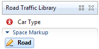
Double-click the
 Road element in the Space Markup section of
  Road Traffic Library palette. The icon of the element should turn into
  . It means that the drawing mode is activated and you can now draw the road point by point in the graphical editor.
-
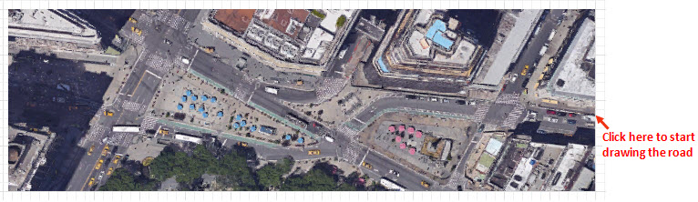
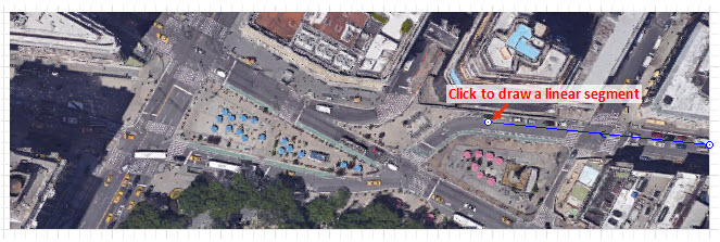
Click in the graphical editor to draw the first point of the road.
-
Continue drawing the road segment by segment. Our road starts with a linear segment. To draw a linear segment, click in the place where you want to put the segment’s end point (see the figure below).
-
The next segment of our road is curved. To draw a curved segment, press the left mouse button at the road’s next turning point (in the beginning of the next linear segment) and move the mouse with the left mouse button being pressed until you get the segment of the required shape. Release the mouse button when finished adjusting the form of the road segment.
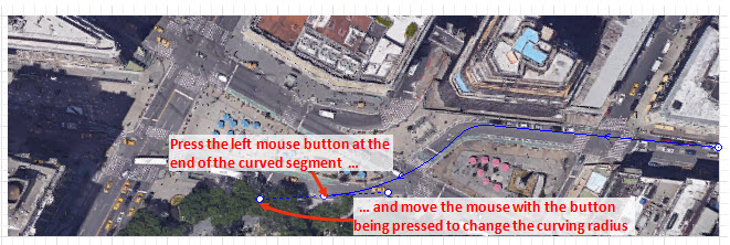
-
Finally put the last point of the road with the double-click.
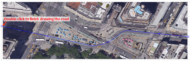
-
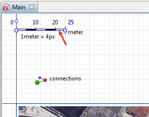
If it is the first road in the model that you are drawing, you will see a message prompting you to change the model scale to 4.0 pixels per meter. We recommend you to follow this advice as the offered scale is frequently used in typical road traffic models. You can set scaling to be performed automatically (as well as turn it off) in the AnyLogic preferences.
Finally you will see the drawn road. It should look like the one in the figure below: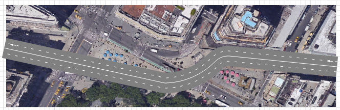
-
Customize the road attributes in the Properties view. By default roads are drawn two-way with two lanes for cars moving in one direction (forward lanes), and two lanes for cars moving in the opposite direction (backward lanes). Broadway is a one-way road with two lanes, that is why you should select the One way option. The number of lanes will automatically decrease to 2. As the result, the road may shift a bit and you may need to adjust the road position.
The arrow on the road indicates the car movement direction.
As you can see, the road is drawn opaque. Let’s make the road semi-transparent to double-check whether the resulting road perfectly matches the road on the map. The transparency setting (as well as traffic direction and lane width) is defined not in the road properties, but in the properties of the road network this road belongs to. -
Select the road network by clicking the road. The first click selects the road itself. The next click selects the road network. Having selected the road network, open the network’s Appearance properties. Click in the Road color control, choose Other Colors... from the list, and set the road color’s Transparency level to 150 as for instance.
- If required, you can also adjust the lane width in the properties of the road network (it will apply to all roads comprising this network). By default, the lane is set to be 3.5 meters wide, and usually we do not change this value. However, if you model roads with broader or narrower lanes, you can tune this setting here.
-
Now you can see how the drawn road matches the road on the map. If it is more narrow or more broad, you should adjust the model scale. If needed, drag the canvas down to see the Scale element above the X-axis and adjust the model scale in its properties. The road width will alter according to the changes you make.
-
In this example, we set the scale ruler to correspond to 25 meters.
Finally you should get the road that looks like the one on the figure below: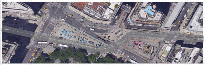
The further road network creation (adding intersections, drawing other roads) is described in Intersection.
- General
-
Name — The name of the road.
Ignore — If selected, the road is excluded from the model.
Visible on upper agent — If selected, the road is also visible on the upper agent where this agent lives.
Lock — If selected, the road is locked. Locked shapes do not react to mouse clicks — it is impossible to select them in the graphical editor until you unlock them.
Visible — Here you specify whether the shape is visible on animation at model runtime, or not. Using the control, choose yes or no.
One way — If selected, the road is one-way. Otherwise, it contains separate lanes for forward and backward traffic.
Number of forward lanes — Specifies the number of lanes with traffic moving forward.
Number of backward lanes — [Visible and applies only if the One way option is disabled] Specifies the number of lanes with traffic moving backward.
Median strip width — [Visible and applies only if the One way option is disabled] Defines the width of the median, which separates the lanes with oncoming traffic.
Median strip color — [Visible and applies only if the One way option is disabled] Defines the color of the median, which separates the lanes with oncoming traffic.
- Position and size
-
X — X-coordinate of the road’s start point.
Y — Y-coordinate of the road’s start point.
Z — [Enabled if the Show in advanced property is set to 2D and 3D or 3D only] Z-coordinate of the road’s start point.
- Points
-
The table located in the Points properties section enables users to view and adjust coordinates of the road turning points.
Here you define relative coordinates, not the absolute ones. The first point always has coordinates (0, 0, 0) that cannot be changed.
Other rows of the table define relative coordinates of the successive points. Coordinates of each point are actually offsets of the corresponding point from the start point along X, Y (and optionally Z) axes correspondingly.
- Advanced
-
Show in — Here you can choose whether you want the shape to be shown both in 2D and 3D animation, or in 2D only, or in 3D only.
Show name — If selected, the road’s name is displayed on the graphical diagram.
You can change a linear shape of any road segment to curved and vice versa as well as edit the curved shape anytime.
To make a road segment linear / curved
- Right click the road in the graphical editor and choose Make Segment Linear/Arc-based from the context menu.
- On hovering your mouse over a segment, you will see the preview of the shape the segment will acquire if you click it. Now click the segment the shape of which you want to change.
- You can change shapes of other segments if needed. When done, click an empty spot on the graphical diagram to switch off this editing mode.
If the shape of the curved segment does not match the shape of the actual road, you can change the shape of the segment with the help of the guiding lines.
To change shape of the curved road segment
- Right-click the road and select Edit Using Guiding Lines from the context menu. The guiding lines will appear for editing points. Left-click the editing line point and drag it around without releasing the left mouse button.
-
You will see multiple handles. Rectangular markers show the end points of the segment, and the straight lines with round shaped handles on their ends — are the guiding lines. Each segment’s end point has got its own guiding line. The guiding lines will appear for each editing point of the road’s curve.
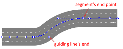
- Drag the end point of the guiding line with your mouse. You will see that the shape of the corresponding curved segment will be changing as you drag your mouse. Release the mouse button when finished adjusting the form of the road segment. You might also need to adjust the length and / or the position of this segment’s other guiding line.
- To exit the editing mode right-click the road and deselect Edit Using Guiding Lines in the context menu or simply click an empty spot on the graphical diagram.
To add a segment to a road
- Right-click the road and select Append line from the context menu.
- Chose which side of the road you want to append the line from. Click the corresponding end point of the road.
- You are in the drawing mode now. You can add as many new segments as you need, both linear and curved.
- Finish drawing by double-clicking at the spot where you want to place the end point of the road.
The arrow drawn on the road in graphical editor indicates the forward movement direction.
![]()
To change the direction of the road
- Right-click the road in the graphical diagram and choose Change Direction from the context menu. The arrow drawn on the road will change its direction.
- Cars
-
Function Description int nCars(boolean isOnForwardSide) Returns the number of cars located in forward or backward lanes of the road depending on the argument value.
isOnForwardSide — pass true to return number of cars located in road’s forward lanes, false to count cars located in backward lanes.int nCarsOnLane(boolean isOnForwardSide, int laneIndex) Returns the number of cars located in the specified lane.
isOnForwardSide — pass true to return number of cars located in road’s forward lane, false to count cars located in a backward lane.
laneIndex — zero-based index of the lane. Lanes are numbered from outmost (index: 0) to inmost.List<Agent> getCars(boolean isOnForwardSide) Returns ordered list of cars located in forward or backward lanes of the road depending on the argument value. The first car in the list is the nearest one to the exit point from road (seems like the first one to exit the road, if there is no acceleration).
isOnForwardSide — pass true to return cars located on road’s forward lanes, false to return cars in backward lanes. - Speed
-
Function Description double averageSpeed(boolean isOnForwardSide, double offset) Returns the average speed in forward or backward lanes of the road (depending on the argument value) in the road segment at the specified offset.
isOnForwardSide — pass true to return speed in forward lanes, false to return speed in backward lanes
offset — offset from the start of the corresponding lanedouble averageSpeed(boolean isOnForwardSide, double offset, SpeedUnits units) Returns the average speed (in the given speed units) in forward or backward lanes of the road (depending on the argument value) in the road segment near the specified offset.
isOnForwardSide — pass true to return speed in forward lanes, false to return speed in backward lanes
offset — Offset from the start of the corresponding lane
units — Speed units constant - Lanes
-
Function Description int getForwardLanesCount() Returns the number of forward lanes. getBackwardLanesCount() Returns the number of backward lanes. void setForwardLanesCount(int forwardLanesCount) Sets number of forward lanes.
forwardLanesCount — new number of forward lanesvoid setBackwardLanesCount(int backwardLanesCount) Sets number of backward lanes.
backwardLanesCount — new number of backward lanes - Median strip
-
Function Description double getMedianStripWidth() Returns median strip width in pixels. double getMedianStripWidth(LengthUnits units) Returns median strip width measured in the given length units.
units — length unit constantvoid setMedianStripWidth(double medianStripWidthInPixels) Sets median strip width in pixels.
medianStripWidthInPixels — specified median strip width in pixelsvoid setMedianStripWidth(double medianStripWidth, LengthUnits units) Sets median strip width measured in the given units.
medianStripWidth — new median strip width
units — length unit constantvoid setMedianStripColor(Color color) Sets the color of the median strip.
color — the new color, if null the median strip is not drawnvoid setMedianStripColor(Paint color) Sets the color (or texture) of the median strip.
color — the new texture, if null the median strip is not drawnColor getMedianStripColor() Returns the color of the median strip, or null if median strip has no color or has texture (in this case getMedianStripTexture() should be used instead). Texture getMedianStripTexture() Returns the texture of the median strip, if the median strip has texture. - Level
-
Function Description Level getLevel() Returns the level, where this road is located. - Visibility
-
Function Description void setVisible(boolean v) Sets the visibility of the road.
v — visibility of the road. If true, road is visible, if false — not visible.boolean isVisible() Returns the visibility of the road. If it returns true, the road is visible, if false — not visible. - Advanced
-
Function Description RoadNetwork getRoadNetwork() Returns road network the road belongs to. List<StopLine> getStopLines() Returns all stop lines belonging to this road. List<ParkingLot> getParkingLots() Returns all parking lots adjacent to this road. List<BusStop> getBusStops() Returns all bus stops adjacent to this road. MarkupSegment getSegment(int index) Returns the segment by its index.
index — the segment index, [0 .. getSegmentCount() - 1]int getSegmentCount() Returns the number of segments. double getWidth() Returns the total width of road segment in pixels. Total width consists of width of all forward lanes, width of all backward lanes and width of median strip. double getWidth(LengthUnits units) Returns the total width of road segment in the given units. Total width consists of width of all forward lanes, width of all backward lanes and width of median strip.
units — length unit constant - Removal
-
Function Description void remove() Removes the road from the presentation. If the road is not a part of presentation, the function does nothing. Removal from the presentation does not necessarily mean removing from the model logic, since logical networks and routes may have been created before the removal and survive it.
-
How can we improve this article?
-