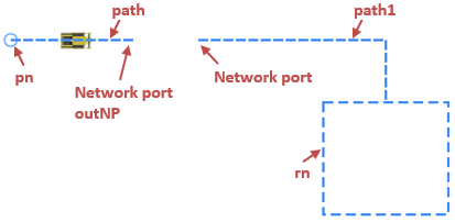
If needed, you can create a network programmatically. Please note that you can do it only on model startup, and the network cannot be modified later.
In this article we look at the code example of the following model:
Demo model: Create Transporter Network by Code Open the model page in AnyLogic Cloud. There you can run the model or download it (by clicking Model source files). Demo model: Create Transporter Network by CodeOpen the model in your AnyLogic desktop installation.We create a network that consists of a point node and a rectangular node, that are connected by two paths. The paths are joined with a pair of network ports and behave like they form one path. Transporters enter the network in the point node. Then they move along the paths to the attractor inside the rectangular node.

To create a network, we use a custom function createLevelAndNetwork which returns the object of the type Level. In the body of the function we provide Java code which builds a network, places it inside a level and initializes the level. The code is the following:
// Create a rectangular node with attractor inside
rn = new RectangularNode();
rn.setPos(300.0, 350.0, 0.0);
rn.setSize(100.0, 90.0);
rn.addAttractor(325.0, 375.0, 4.7);

// Create a point node
pn = new PointNode();
pn.setRadius(5);
pn.setLineColor(dodgerBlue);
pn.setPos(50.0, 300.0);

// Create a path from a source node to a network port
Path path = new Path( );
path.setBidirectional(true);
path.addSegment(new MarkupSegmentLine(50.0, 300.0, 0.0, 150.0, 300.0, 0.0));
path.setSource(pn);
NetworkPort outNP = path.createPort(PathEndType.END);

// Create a path from a network port to a target node
Path path1 = new Path( );
path1.setBidirectional(true);
path1.addSegment(new MarkupSegmentLine(200.0, 300.0, 0.0, 350.0, 300.0, 0.0));
path1.addSegment(new MarkupSegmentLine(350.0, 300.0, 0.0, 350.0, 350.0, 0.0));
path1.createPort(PathEndType.BEGIN, outNP);
path1.setTarget(rn);

// Create a network with the paths and the nodes
n = new Network( this , "myNetwork");
n.addAll(rn, pn, path, path1) ;

// Create a level with the network and initialize the level
Level level = new Level(this, "myLevel", SHAPE_DRAW_2D3D, 0);
level.add(n);
level.initialize(); // Cannot be changed after initialization!

return level;First, we create a rectangular node and define its position and size. The position is defined by the X-Y-Z coordinates of the upper left corner of the node. The size is defined by the width and height of the node in pixels.
Next, we add an attractor with the help of the addAttractor() function of the node where we provide the attractor’s X and Y coordinates and orientation angle (in radians) as arguments. We don’t need to specify this exact attractor as transporter’s destination in the MoveByTransporter block, since if there is an attractor in the node, the transporter will always go to it anyway.
We create a point node and define its radius, line color, and position. The position is defined by the X and Y coordinates of the point node’s center.
Now we create the first path that will connect the point node to the first network port. We specify that it supports movement in both ways. To do this, we pass true as the bidirectional argument of the setBidirectional() function of the path.
The path consists of one segment. The segment is created via the MarkupSegmentLine constructor passed as an argument of the addSegment() function. This constructor accepts six arguments: X, Y, Z coordinates of the line’s start point followed by the end point’s coordinates.
Next, we connect the path to the point node. Since we connect the start point of the path, we use the setSource() function of the path.
The following line of code creates a network port and connects it to the end point of the path using the path’s function createPort(). The function’s argument specifies that the network port is created at the end point of the path:
NetworkPort outNP = path.createPort(PathEndType.END);Then the second path, path1, is created in the similar manner. It consists of two segments. We add them in the order of their placement from the starting point of the path.
The following line of code creates a network port and connects it to the path1, similarly to the line above. This time it creates the network port at the starting point of the path (the argument this time is PathEndType.BEGIN). And the second argument is used to specify the network port (outNP) to pair the just created network port to.
path1.createPort(PathEndType.BEGIN, outNP);Next, we connect the path to the rectangular node: path1.setTarget(rn). Since we connect the node to the end (or target) point of the path, this time we use the setTarget() function.
We now have all the elements that are needed to create a network. In the Network constructor, we provide the reference to the agent where this network will be placed (this) and the name of the network ("myNetwork").
After the network is created, we add nodes and paths that we created earlier to it by providing them as arguments of the network’s add() function:
n.addAll( rn, pn, path, path1 );The last object we need to create is the level where the network will exist. We pass the agent where the level will be added (this) and the name of the level, and specify drawing mode (2D, 3D or both) and the network’s Z-coordinate (which is zero in our case):
Level level = new Level(this, "myLevel", SHAPE_DRAW_2D3D, 0);Next, we add the network to the level and initialize the level itself.
Next, we specify that the function returns the created level.
Finally, we add the created level to the presentation group to make it visible at runtime. To do this, we call the add() function of the presentation group in the On startup action of the Main agent (Agent actions properties section) and pass the myLevel variable as the argument.
-
How can we improve this article?
-

