

Next, there are trucks that deliver products from the distributor to retailers.
Let us create the whole fleet at once as a population.
Create a vehicle fleet
- Drag the
 Agent element from the
 Agent palette onto the
Main diagram. Choose to create a Population of agents in the first step.
Agent palette onto the
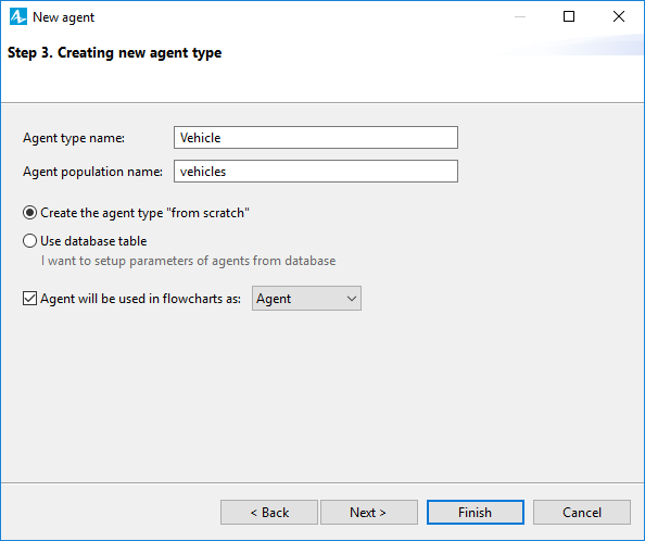
Main diagram. Choose to create a Population of agents in the first step. - On the next page of the wizard, select the I want to create a new agent type option. Click Next.
- Type Vehicle in the Agent type name field. The specified name will autofill the Agent population name field with vehicles.
- Select the Agent will be used in flowcharts as option and leave the set by default Agent. Click Next to proceed to setting up the agent’s animation.
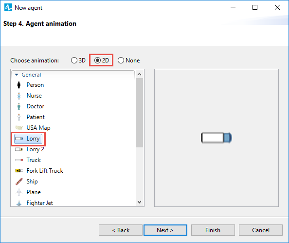
- Set the animation figure, like you did for other agents. Select the 2D option and choose the Truck shape in the list. Click Next.
- We will skip the Agent parameters step. Click Next.
- Now we will define the number of agents living in this population. Let us assume that we have 15 trucks in our supply chain. Type 15 in the Create population with ... agents field.
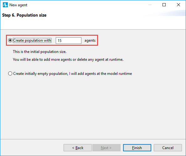
- Click Finish. You will see the population
vehicles residing on
Main with its animation on the map.
Place the fleet at the distribution center
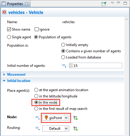
In our model, all trucks initially reside at the distributor’s location, where they wait for orders to be processed.
- Select the
vehicles population and choose the node that we set for the
distributor as the trucks' initial location.
Run the model. The trucks will appear at the distributor’s location.
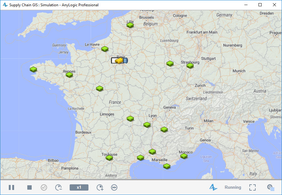
You will see that the truck shapes are rather big.
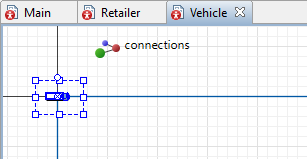
To decrease the truck size, open the
![]() Vehicle agent diagram by double-clicking Vehicle in the
Vehicle agent diagram by double-clicking Vehicle in the
 Projects view, then zoom in the diagram and then decrease the size of the truck shape.
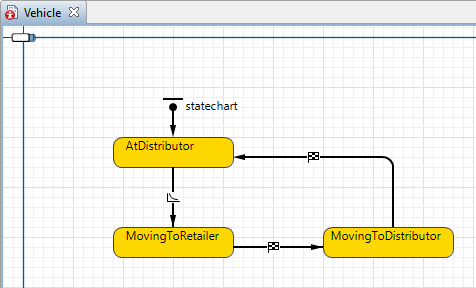
Now let us define the truck’s movement logic. We will define it using a statechart. Statechart is one of the most powerful and easy-to-use AnyLogic tools that allows users to define the object’s behavior as a sequence of states. For instance, for the equipment it could be Busy and Idle.
In our case the statechart will define the truck’s movement logic. Since we are creating not a real complex supply chain, but just a simple toy model to show you the most important agent-based AnyLogic tools, the logic in this one will be significantly simpler than in real life.
The trucks in our model initially wait for orders at the distributor’s location. Once the order is assigned, the truck moves to the retailer that placed this order. On reaching the retailer, the truck begins the unloading process, whereupon it moves back to the distributor to fulfil the next order (if any).
Define the truck movement
- Open the diagram of the
Vehicle agent type by double-clicking the Vehicle item in the
Projects view.
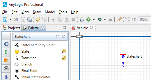
- Open the
 Statechart palette in the
 Palette view.
 - To start drawing a statechart, drag the
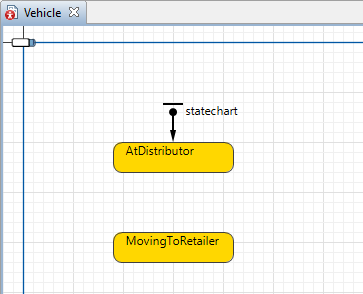
 Statechart Entry Point element onto the
Vehicle diagram. This element defines the starting point of the whole statechart. Each statechart must have one statechart entry point element. The element will be highlighted in red. It means that it is not connected to other statechart elements and the current statechart is interpreted by AnyLogic as erroneous / incomplete.
Statechart Entry Point element onto the
Vehicle diagram. This element defines the starting point of the whole statechart. Each statechart must have one statechart entry point element. The element will be highlighted in red. It means that it is not connected to other statechart elements and the current statechart is interpreted by AnyLogic as erroneous / incomplete.
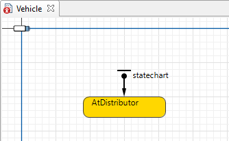
- Now, let’s add states. Drag the
 State element from the palette and connect it to the statechart entry point. Name the state AtDistributor. This will be the initial state for our trucks.
- Add another state below the first one. The next state models the truck’s movement to a retailer. Name it MovingToRetailer.
- We have drawn two states. Now it is time to define how the agent (truck) will be switching from one state to another. For this purpose, we will use a transition, which is another principal element of a statechart. To draw a transition, double-click the
 Transition element in the
Statechart palette to activate its drawing mode. Now draw a transition by clicking inside the state that it goes from, then click the border of the state that it leads to. If the elements are connected successfully, the point of connection will be highlighted in the green color.
Transition element in the
Statechart palette to activate its drawing mode. Now draw a transition by clicking inside the state that it goes from, then click the border of the state that it leads to. If the elements are connected successfully, the point of connection will be highlighted in the green color. - To relocate the transition’s trigger icon, select the transition and drag the icon to a new place.
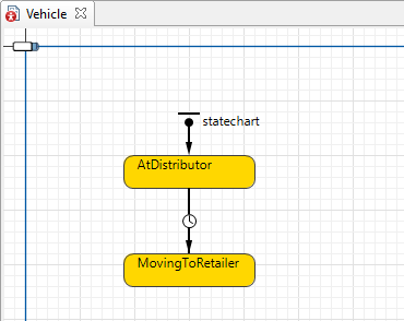
- Right now we are creating a simple model where trucks will start their movement to a randomly chosen retailer. Transitions may be triggered by events of various types: on timeout expiry, with the specified occurrence rate, on agent arrival to the destination, etc. By default Timeout is the trigger type of any transition, that is why it has a clock icon:
 . We will change the transition’s trigger type to Rate.
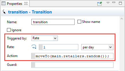
- In the Action edit box, write Java code as shown on the screenshot above: moveTo(main.retailers.random());
This action will send the truck containing this statechart to a randomly selected retailer.When typing the Java code, use the code completion wizard, accessible by pressing Ctrl + Space (macOS: Alt + Space) in the code field. It provides you with the list of available functions and model elements, so you can simply choose the required item from the list and avoid mistypes when referring to it.moveTo() is a function that initiates the agent movement. Using the function argument, we define the movement destination. You can make an agent move to another agent, a node, or even a geographic location. In our case we send the truck to a randomly selected retailer. In this model retailers are defined as the retailers agent population living in
Main agent.
Trucks are defined in the similar way — as vehicles agent population.
As you understand, both populations live on the same level of the model hierarchy, which means that to access an agent of another population, we first access the upper-level agent of the Main agent type as main, and then we access its internal field by putting the dot: main.retailers. This way we get access to the
retailers population.
To get one randomly selected agent from the population, we use the population’s function random(): main.retailers.random(). The semicolon at the end marks the end of the Java statement. - In this tutorial, we will start with simple logic. After reaching the retailer, the truck will move back to the distributor. We will simulate this process using the same approach that we have previously used to simulate returning of a truck to a retailer. Add one more state and name it MovingToDistributor.
- Add transition leading from the
MovingToRetailer to the
MovingToDistributor state. The truck will get into this state on reaching the retailer. Navigate to the transition’s properties and set the Triggered by parameter to Agent arrival. The transition’s icon will change to
 .
.
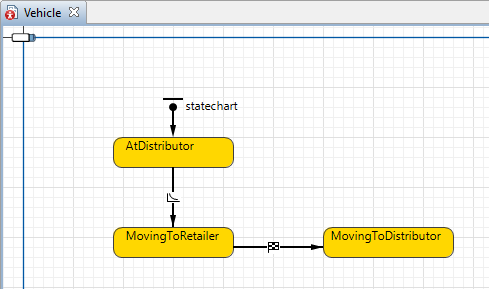
- For this transition, type moveTo(main.distributor); in the Action field. Having reached the retailer, the truck will change its state to
MovingToDistributor, since this transition is set up to be triggered by agent arrival. The function called in the Action field of this transition initiates the truck to further move from the retailer to the distributor.
- Add one more transition leading from
MovingToDistributor to
AtDistributor state.
- Set this transition to be Triggered by: Agent arrival. Once the truck arrives to its distributor, it is back in the
AtDistributor state, ready to take and deliver another order.
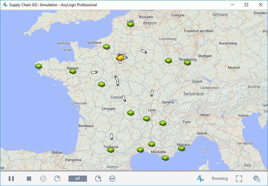
Run the model and observe the trucks moving to retailers and back to the distributor located in Paris.
-
How can we improve this article?
-