

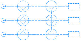
A network is a set of nodes interconnected with segments. You draw a network when you need network- or layout-based modeling. Typically, it is used when the modeled processes take place in a certain physical space and include movement of agents and resources. For example, this can be a hospital or a plant logistics process.
You define the network topology by drawing specific space markup elements (nodes and paths), for example, over a facility map used as a background. In the network, a node defines the place where agents may stay, while paths connecting nodes define the routes that agents may take when moving from one node to another. Movement is always done along the shortest path between the origin and the destination nodes. Agents and resource units can have individual speeds and these speeds can change dynamically. For example, you can set different speeds for the loaded and the unloaded forklift truck. It is assumed that segments have unlimited capacity and that agents moving along a segment do not interfere with each other.
The  Network element is automatically created when two network elements (a path and a node, or two paths) are connected together. AnyLogic also automatically creates a network for every single path element that is not connected to any other network elements.
You can have multiple networks in one model.
When configuring the Visible, Z and Show in network properties, remember that all network elements will inherit the values of these properties.
To select a network
- Click on any element belonging to the network. The element will be selected.
- Click on this element again to select the entire network.
- General
-
Name — The name of the network. The name is used to identify and access the network from code and flowchart blocks properties.
Ignore — If selected, the network is excluded from the model.
Visible on upper agent — If selected, the network is also visible on the upper agent where this agent lives.
Lock — If selected, the network is locked. Locked elements do not react to mouse clicks — it is impossible to select them in the graphical editor until you unlock them. It is frequently needed when you want to prevent editing the element while placing other elements over it.
Visible — Here you specify whether the network is visible on animation at model runtime, or not. Using the control, choose yes or no.
Level — Level on which this network is located.
Z — Z-coordinate of the network.
- Advanced
-
Show in — Here you can choose whether you want the shape to be shown both in 2D and 3D animation, or in 2D only, or in 3D only.
Note that the functions that modify the network can only be called before the network is initialized.
| Function | Description |
|---|---|
| Node getNearestNode(Point givenPoint) |
Returns the node closest to the provided Point. givenPoint — the point. |
Node getNearestNode(double x, double y, double z, Point out) |
Returns the node closest to the point with the provided X, Y, and Z coordinates. x, y, z — the X, Y, and Z coordinates of the point. out — The output point. The function itself returns the node, and in out you can store the coordinates of the point in this node that will be closest to the given coordinates. |
| Node getNearestNode(Point p, Point out) |
Returns the node closest to the provided Point. givenPoint — the point. out — The output point. The function itself returns the node, and in out you can store the coordinates of the point in this node that will be closest to the given coordinates. |
| Node getNearestNode(Agent agent, Point out) |
Returns the node closest to the specified agent. agent — the agent. out — The output point. The function itself returns the node, and in out you can store the coordinates of the point in this node that will be closest to the given coordinates. |
| Agent getSpace() | Returns the agent where this network is defined. |
| double getZ() | Returns the network’s Z-coordinate. The Z-coordinates of the elements belonging to this network are relative to the Z of the network. |
| Level getLevel() | Returns the level on which this network is located. |
-
How can we improve this article?
-