

AnyLogic models are hierarchically organized, since agents may encapsulate other agents to any desired depth. This enables you to decompose a model into as many levels of detail as required, since each agent typically represents a logical section of the model. Each AnyLogic model has a top-level agent which contains agents of other types which, in turn, may contain other agents, and so on. This way, the hierarchical tree of agents is constructed. Encapsulation also enables you to hide some complexities of a modeled object.
In AnyLogic agent may define space for the agent populations present on its diagram. Agents defining spaces can be hierarchically organized (for example, agents-companies can live in one space and agents-employees can live in local company spaces). Agent population can belong to at most one space.
AnyLogic model is a tree of agents encapsulating each other. The root of that tree is called the top-level agent. The top-level agent represents the highest abstraction level of your model. When you specify the agent type to be the top-level agent of your model, you tell AnyLogic where to start the model creation.
Unlike some other simulation tools with well-defined model structures, in AnyLogic you can change the model structure in a very simple manner. You can simply create several experiments with different top-level agents in the same model and adjust your model structure by running one or another experiment.
To set a top-level agent for an experiment
- Click the experiment in the Projects view.
- In the General section of the experiment properties, select agent type from the Top-level agent drop-down list.
When the user creates a new model, one agent type, Main, is created by default. Usually this agent type acts as the space for other agents. The user creates agent types and adds single agents and agent populations onto Main diagram.
A common and simple case in agent-based modeling is to have two agent types, one of which forms a population in the top-level Main agent. For example, a model could have two agent types, where a population of clients agents live in Main, while each individual Client may have its own parameter values and other attributes. This structure is often sufficient for many real-world use cases. You can explore this setup in the example model:
Demo model: Cell Telecom Market Open the model page in AnyLogic Cloud. There you can run the model or download it (by clicking Model source files). Demo model: Cell Telecom MarketOpen the model in your AnyLogic desktop installation.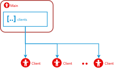
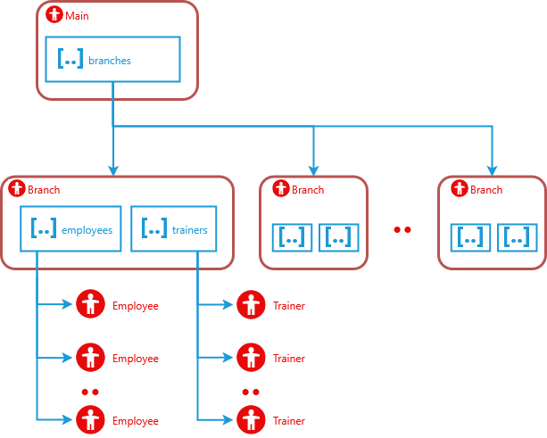
Embedded agents may embed other agents, and so on, there is no limitation on the number of levels of hierarchy within the model. The following demo model has two levels of hierarchy.
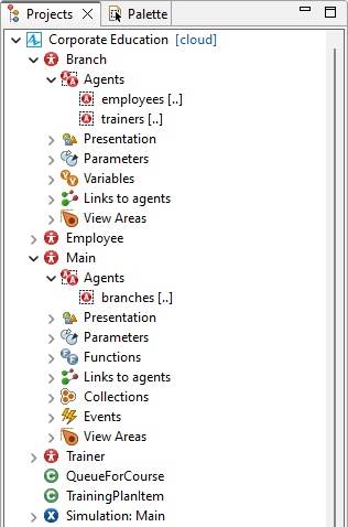
Demo model: Corporate Education Open the model page in AnyLogic Cloud. There you can run the model or download it (by clicking Model source files). Demo model: Corporate EducationOpen the model in your AnyLogic desktop installation.There are four agent types in this model: Main (acting as a space for other agents), Branch, Employee, and Trainer. Inside Main, there is the branches population containing multiple agents of the Branch agent type. In its turn, inside each Branch agent there are two populations, employees and trainers.
This is how it looks in the Projects view in AnyLogic:
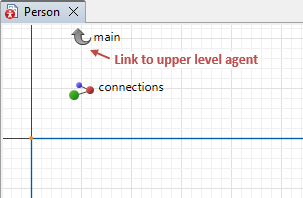
When you embed one agent within another, AnyLogic automatically creates a link to the upper level agent on the graphical diagram of the embedded agent.
This link is a non-removable element with a label displaying the name of the upper level agent. On the graphical diagram, you can find it above the X-axis:
Double-click the link to navigate to the diagram of the parent (owner) of the agent.
This element is not shown in the Projects view.
This element helps you to understand how you can refer in the code of the agent to the agent that lies on the upper level of model hierarchy. You refer to the upper level agent by the name of this element. To know more about navigating in code to various items of a hierarchical model, please refer here.
If the agent is embedded into several other agent types, you will see several corresponding Link to upper level agent elements, one per each embedding.
- General
-
Name — The name of the element. This element helps you to understand how you can refer in the code of the agent to the agent that lies on the upper level of model hierarchy. You refer to the upper level agent by the name of this element. The name of the link is defined automatically: it has the same name as the upper-level agent but spelled in lowercase.
You can not change the name of the link to the upper level agent.Show name — If selected, the element name is shown on the diagram.
Ignore — If selected, this element is excluded from the model.
Visible — Here you specify whether the element is visible on the animation at the model runtime, or not.
-
How can we improve this article?
-