

You’ve now seen many of the features that help make AnyLogic such a powerful modeling tool. But there are others you haven’t touched, and one of the most exciting is 3D animation.
 Camera objects of AnyLogic allow you to define the view that displays in the
 3D Window. In essence, the camera object “shoots” the picture that you see.
You can also create several camera objects to show different areas of the same 3D scene or to show a single object from different points of view. If you use more than one camera object, you can easily switch from one view to another at runtime.
- On the
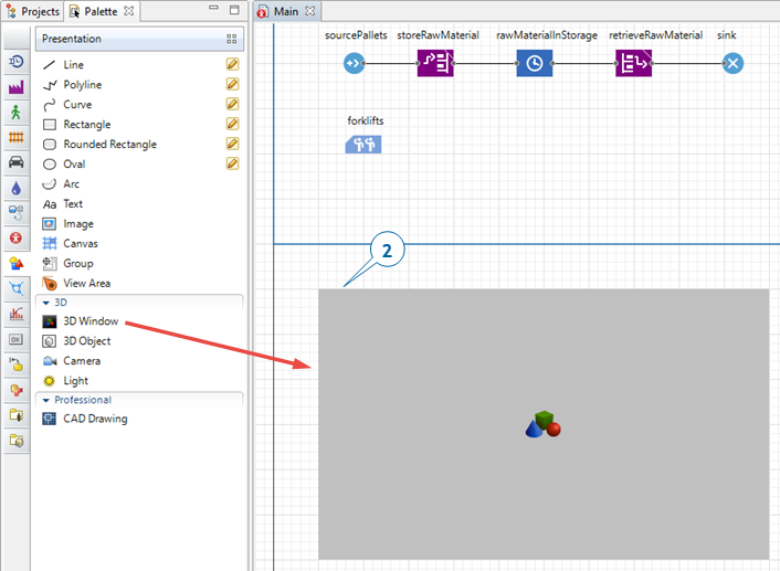
 Presentation palette palette, drag the
Camera object on to the
Presentation palette palette, drag the
Camera object on to the
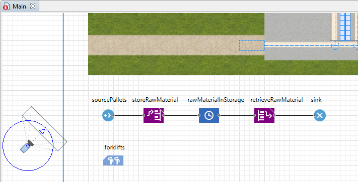
 Main diagram so it “shoots” the job shop layout.
-
Drag the
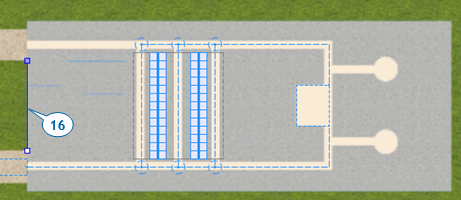
3D Window element on to the Main diagram, and then place it below the process flowchart and the blue frame line.
3D Window
In addition to having the option to add several cameras to your model, you can also add several 3D windows that will each display the same 3D scene from a different point of view.
- Let the camera “shoot” the picture for the
3D Window. In the
3D Window
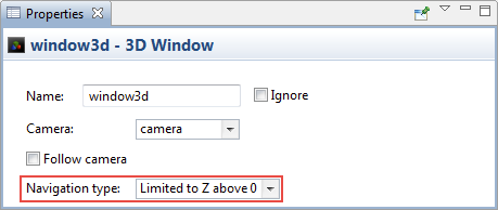
 Properties view, click camera in the Camera list.
 -
Prevent the camera from shooting the picture from under the floor by selecting the option Limited to Z above 0 from the Navigation type list.
-
Run the model.
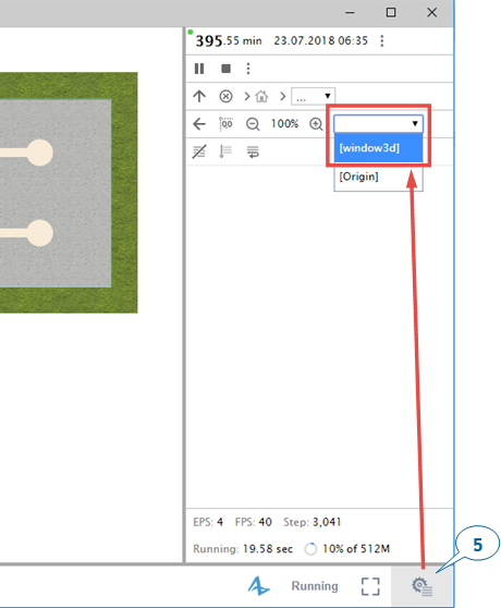
When you create a 3D window, AnyLogic adds a View Area that allows you to easily navigate to the 3D view at runtime. To switch to this 3D view while the model is running, click the rightmost control Toggle Developer panel and select [window3d] from the select view area to navigate list.
-
Do one or more of the following to navigate in 3D at runtime:
- To move the camera left, right, forward or backward, drag the mouse in the selected direction.
- To move the camera closer to or further from the scene’s center, rotate the mouse’s wheel.
- To rotate the scene relative to the camera, drag the mouse while you press and hold Alt (macOS: Option key) and the left mouse button.
-
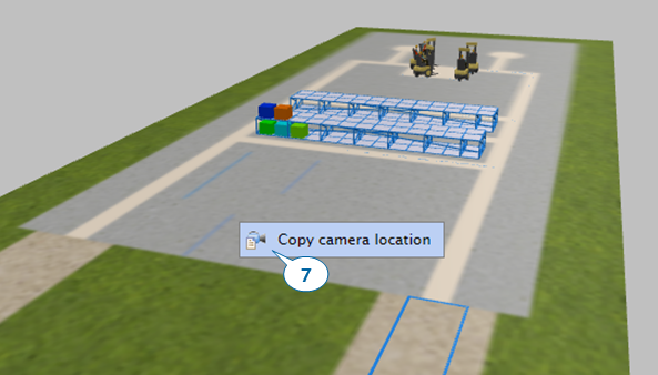
Choose the view you want to display at runtime, right-click (macOS: Ctrl + click) inside the 3D scene, and then click Copy camera’s location.
- Close the model’s window.
-
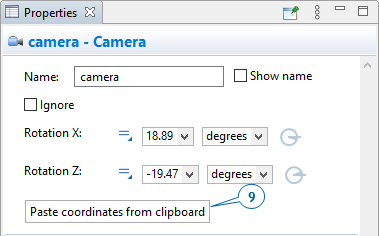
On the camera’s
Properties view, apply the camera location you selected during the previous step by clicking Paste coordinates from clipboard.
 If you can’t locate the camera, you can use the
 Projects view. It will display camera under the
Main agent’s Presentation branch.
Projects view. It will display camera under the
Main agent’s Presentation branch.
- Run the model to view the 3D view from the new camera position, and then close the model window.
-
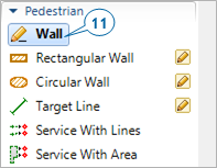
Expand the Pedestrian area on the
 Space Markup palette and then double-click the
 Wall element’s icon to enable wall drawing mode.
-
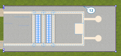
Do the following to draw walls around the job shop layout’s working area:
- Click the position in the graphical editor where you want to start drawing the wall.
- Move the pointer in any direction to draw a straight line, and then click at any point where you want to change direction.
- Double-click at the point where you want to stop drawing the wall.
-
Do the following to change the wall’s fill color and texture:
- In the
Properties view of the wall, expand the Appearance section.
- In the color menu, click Other colors.
-
In the Colors dialog, select the color that you want to apply to the wall from the palette or the spectrum.
You can also set a transparency level (use Transparency slider in the Colors dialog) or customize the wall with any provided texture (click the Textures… item in the colors menu).
- In the
- Change the wall’s Line width to 1 pt.
-
Go to the wall’s Position and size section and change the Z-Height to 40.
AnyLogic automatically sets the shape’s height to 20 pixels to ensure it has volume in a 3D view, but we’ve now increased its height to 40 pixels. -
Draw another wall between the exits and then change the settings in the second wall’s
Properties view to match the first wall.
-
Run the model and view the 3D animation.
You’ll see that our model’s animation uses randomly colored shapes to represent pallets, but we’ll correct the problem by creating an agent type that defines a custom animation for pallets. -
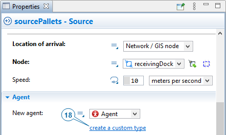
In the sourcePallets block’s
Properties view, under the New agent list, click create a custom type.
-
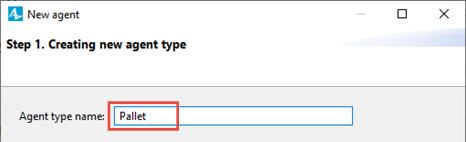
In the New agent wizard, do the following:
- In the Agent type name field, type Pallet.
-
Click Next.
- On the next page of the wizard, expand the Warehouses and Container Terminals section in the list on the left, and then click the 3D animation figure Pallet.
- Click Finish.
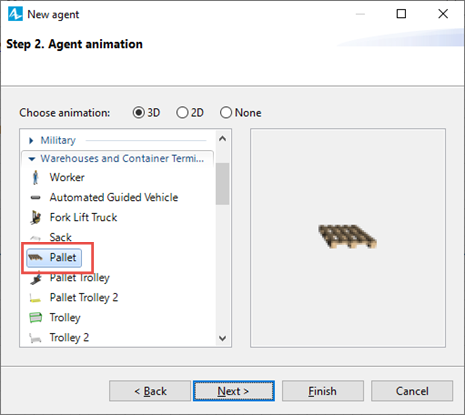
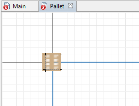
AnyLogic creates the Pallet agent type and opens the Pallet diagram that will display the animation that we selected in the wizard.
- In the properties of the Pallet agent type, expand the Agent in flowcharts section, and select Material Item from the Use in flowcharts as drop-down list. Now agents of the Pallet type will have the additional functionality, which may be useful while these agents are processed by Material Handling Library blocks. Specifically, now pallet agents have explicitly defined dimensions (if you expand the Dimensions and movement section of the Pallet agent type’s properties, you will see the Length, Width, and Height fields.)
-
Using the Zoom toolbar, enlarge the Pallet diagram to 300%, and then move the canvas to the right and down to view the axis’ origin point and pallet animation shape.
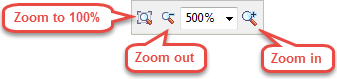
Enlarging or reducing the view
AnyLogic’s Zoom toolbar lets you enlarge or reduce the view of a graphical diagram:
-
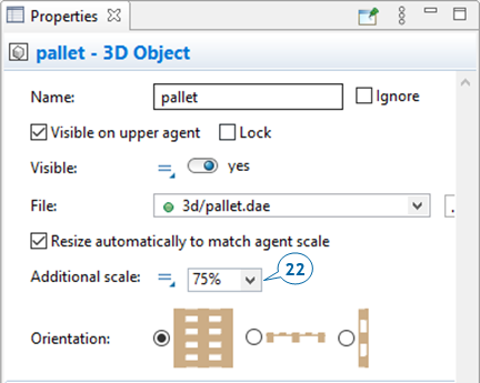
Since the pallet shape appears to be too large and does not fit into the placeholder corresponding to this material item’s dimensions, select it by clicking, and change its Additional scale to 75%.
-
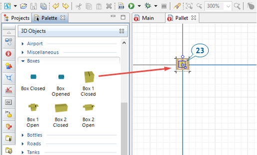
Add product animation on top of the pallet animation. On the
 3D Objects palette, expand the Boxes area, and drag the Box 1 Closed object on to the pallet.
- Change the box’s Additional scale to 125%.
-
In the box’s
Properties view, expand the Position section, and then change the box’s Z coordinate to 2.
Our change reflects the fact that we want to place boxes on the pallets and each pallet’s height is about 2 pixels. -
Change the zoom level back to 100% by clicking the toolbar’s Zoom to 100%
 button.
-
Return to the
Main diagram.
If you open the sourcePallets block’s Properties view, you’ll see Pallet is selected as New agent. This block will generate agents of the Pallet type.
-
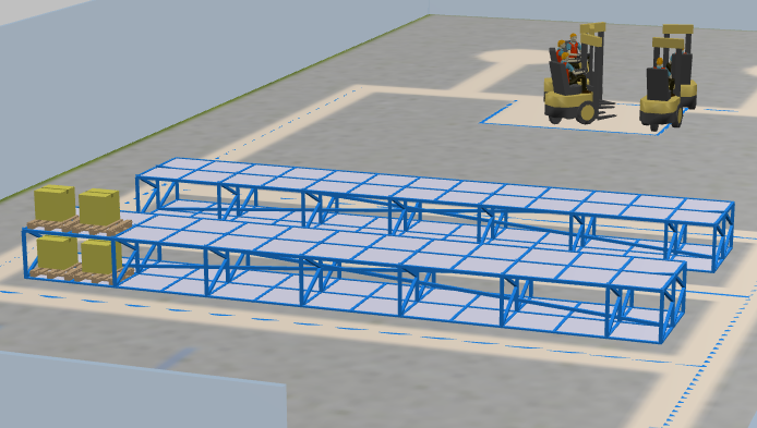
Run the model.
You’ll see pallet shapes have replaced the multicolored shapes. However, if you zoom in the 3D scene, you’ll notice that the forklift trucks aren’t transporting pallets. We’ll correct this problem by moving our model’s pallet animation in a way that allows the forklift trucks to pick up the pallets.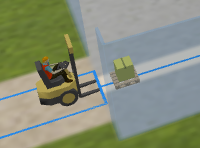
-
In the
Projects view, double-click the ForkliftTruck agent type to open its diagram and then move the forkliftWithWorker figure one cell to the right.
The animation shape is now in the correct location and our model’s pallets are aligned with the forklift trucks’ forks.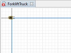
- To change this, select the storage in the graphical editor, then expand the Appearance section of its properties, and set the Occupied cells animation setting to agent animation.
-
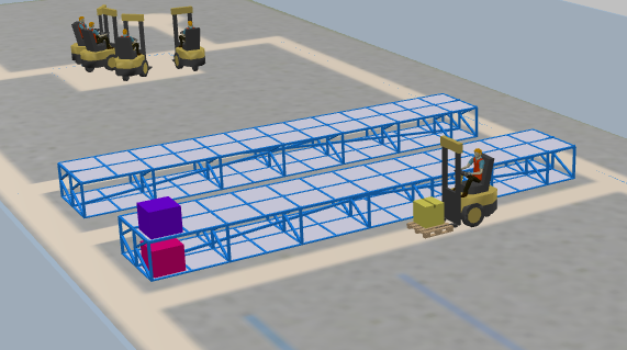
Run the model and you will see that the items stored in the storage are visualized using the chosen 3D models.
The view area expands the 3D animation scene to the model window’s full size.
Our next step will be to add product animation on top of the pallet animation, but we’ll first enlarge the view to give us a closer look at the pallet.
However, when the pallets with products are stored in the storage cells, they are visualized not with 3D models, but with randomly colored cubes. This happens because the storage by default is set to optimize its performance by using primitive shapes to animate the stored items.
-
How can we improve this article?
-