

This is the final phase of the model development.
Add more animation elements
- You can add some background for the agents animation with the help of the presentation shape Rectangle. Double-click
 Rectangle in the
 Presentation palette to enable the drawing mode. Then, click in the graphical editor of
 Main and drag the rectangle without releasing the mouse button until it takes necessary form.
 - Go to the properties section Appearance and select the texture Grass as Fill color and No color for Line. Mind the Z and Z-Height properties. For instance, if Z-Height is set to 10, you can set Z to -10, otherwise other animation figures will “drown” in this background because the surface they are moving on is 0 on Z coordinate.
- Now, since the rectangle is the latest shape added on this graphical editor, it is displayed over our agents’ animation figures. Right-click the rectangle area and select Order > Send to back.
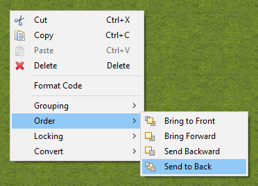
- You can also right-click the
MC animation figure hangar here and select Order > Bring to front to “hide” the transport behind it.
- In order to enable 3D animation, open the
Presentation palette and drag
 3D Window to the graphical editor. Then you can configure its Properties: resize or change color.
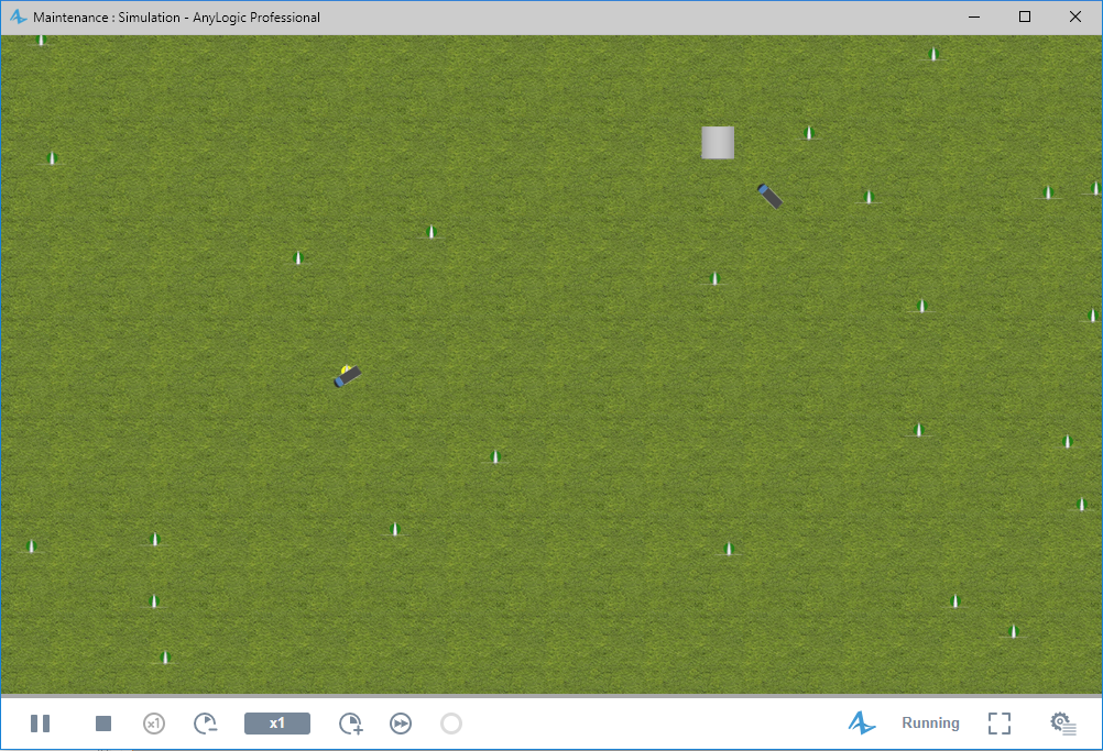
Run the model
- Run the model.
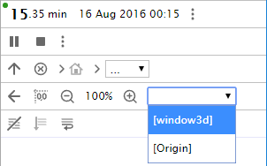
- When you create a 3D window, AnyLogic adds a view area that allows you to easily navigate to the 3D view at runtime. To switch to this 3D view while the model is running, open the developer panel by clicking the
 Developer panel control in the right corner of the control panel. In the developer panel, expand the
  select view area to navigate list and select [window3d] from the list.
- Navigate through the 3D scene using the commands described below:
In order to Use the mouse as described here Move the scene 1. Press the left mouse button in the 3D view and hold the mouse button pressed.
2. Move the mouse in the required direction.Rotate the scene 1. Press Alt key (macOS: Option key) and hold it pressed.
2. Click in the 3D scene window and, while holding Alt and the left mouse button down.
3. Move the mouse in the required rotation direction.Zoom in / out of the scene 1. Scroll the mouse wheel in the 3D window away from / towards you. 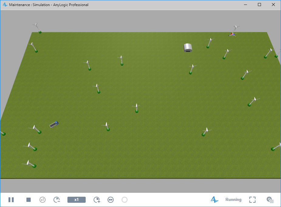
- You can control the running model in several ways:
 Pause or
  Stop the execution,
  Speed up or
  Slow down.
 - You can also observe the individual agents. In the developer panel, expand the
 select agent to dive list and select turbines[25] from the list. In the square brackets you see the number of agents living in this population. Having selected this item in the list, you will see the diagram of the first agent of the turbines population. You can navigate to any other agent of this population by entering the index of the required agent in the control to the right. In this way you can explore and observe any agent in the model.
As you can see, trucks and helicopters park exactly at the turbine location, making the animation a bit weird. To improve this point, you can slightly shift the turbine animation from the turbine’s logical location. To do this, open the
![]() Turbine diagram and slightly move the turbine’s animation shape up (e.g. place the blades along the X-axis). If you run the model now, the animation will look perfect.
Turbine diagram and slightly move the turbine’s animation shape up (e.g. place the blades along the X-axis). If you run the model now, the animation will look perfect.
We have completed the model creation. Now it’s up to you to add some analytics and probably perform the optimization experiment.
Demo model: Maintenance — Phase 7 Open the model page in AnyLogic Cloud. There you can run the model or download it (by clicking Model source files). Demo model: Maintenance — Phase 7Open the model in your AnyLogic desktop installation.-
How can we improve this article?
-