

After curing, the electrodes must be wrapped in isolating envelopes before their terminals are connected to each other to form electrode groups. We will start modeling this production step with adding the necessary elements to the layout.
Draw the layout
- Double-click the
 Conveyor element in the Material Handling section of
 Space Markup palette.
 -
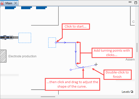
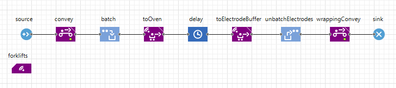
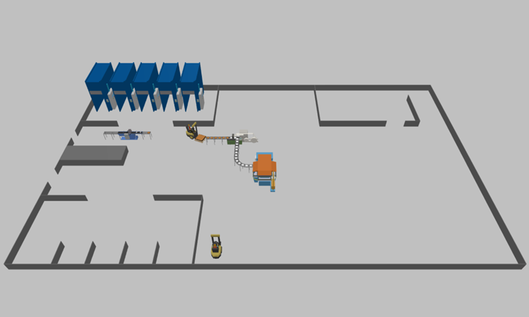
You are now in the drawing mode. Draw the conveyor over the layout as shown in the figure below.
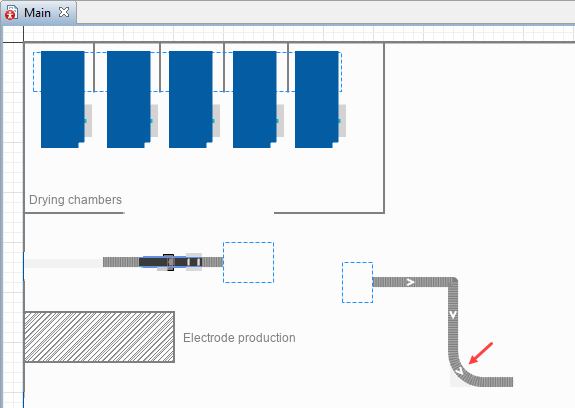
- Click on the border of the node (preassembleElectrodeBuffer) to start drawing the conveyor.
- Draw two straight segments with mouse clicks at the segment ends (turning points of the conveyor).
- Draw a circular segment by pressing (and holding!) the mouse button at the end of the circular segment and dragging the mouse to adjust the shape of the curved segment.
- To draw the last segment and finish drawing the conveyor, double-click at the end point of the conveyor.
-
In the conveyor’s properties, specify the following:
- Name: wrappingConveyor
- Material item type:
 Electrode
 - Z: 20
- Width: 0.5 meters

- Drag the
 Station element from the
 Material Handling Library palette and place it on the
wrappingConveyor:
Material Handling Library palette and place it on the
wrappingConveyor:
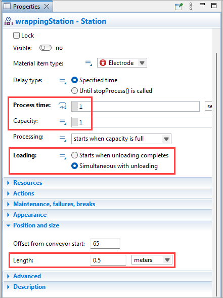
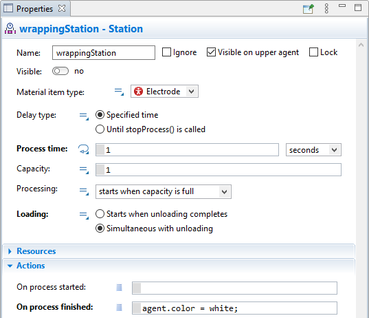
- Name it wrappingStation.
- In the station’s properties switch the Visible parameter to no.
- Adjust the
wrappingStation parameters as follows:
-
General:
- Process time: 1 second
- Capacity: 1 (default)
- Loading: Simultaneous with unloading
-
Position and size:
- Length: 0.5 meters
-
General:
- Next, we will define the separate areas where the assembly process will take place. The electrodes will pass through each area during different stages of processing. We will use the
 Rectangular Node elements to mark these areas:
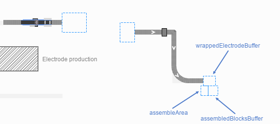
-
wrappedElectrodeBuffer — a temporary storage location for wrapped electrodes before they are collected into blocks.
Width: 25
Height: 20 -
assembleArea — an area where the blocks are assembled.
Width: 15
Height: 20 -
assembledBlocksBuffer — a temporary storage location for assembled blocks of electrodes.
Width: 20
Height: 20
Make sure the dimensions and placement of these nodes exactly correspond to the image above and the instructions give here, since the nodes must fit the 3D animation object which we will add during the next step. -
- In the properties of all these nodes specify the following:
- Visible: no
- Location layout: Arranged
- Z: 20
Add the 3D animation
- Drag the Plate Enveloper 3D object from the Manufacturing section of the
 3D Objects palette to the
Main graphical diagram.
3D Objects palette to the
Main graphical diagram. - In the displayed Auto scale 3D object dialog box click the Yes button.
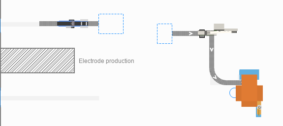
- Adjust the placement of the 3D object over the
wrappingStation as displayed in the image below:
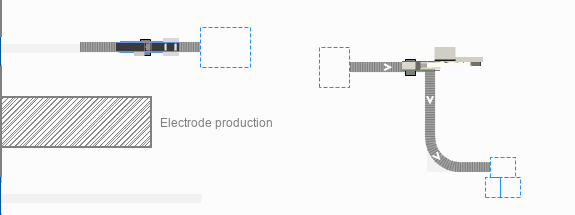
- In the same way, use the COS Machine 3D figure from the Manufacturing section of the
3D Objects palette to create the assembly area animation.
-
In the properties of the shape, set the Additional scale: 160%.
There is no preset value like this in the drop-down list that sets the property value, so you need to specify this value manually — or simply copy the value from this tutorial and paste it into the property.This is a complex 3D object, and you need to set the scale for both of the elements that make it up. Click through the 3D object to select its parts. The first click selects the whole object. The second click selects the first part, and the third click selects the second part. -
Use the handle to rotate the 3D figure 90 degrees to the right. Use the figure below as a reference for proper placement:

Now, let’s define the logic behind the electrodes wrapping process.
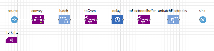
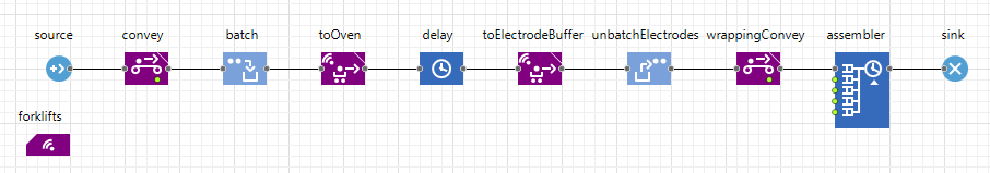
Add the wrapping logic to the flowchart
Before being wrapped in the envelopes, the electrodes must be removed from the batches.
- Drag the
 Unbatch block from the
 Process Modeling Library palette to the
Main graphical diagram and add it to the flowchart before the sink block.
Process Modeling Library palette to the
Main graphical diagram and add it to the flowchart before the sink block. - Name the block unbatchElectrodes.
- In the Element type property, select
Electrode.
We want the unbatched electrodes to appear directly on the
wrappingConveyor which will move them to the wrapping station. Specifically, we want the electrodes to appear at the conveyor’s starting point. We will use the conveyor’s API to obtain the coordinates of this point.
- Clear the Elements appear in batch location check box.
- In the New location property, select the (x, y, z) option.
-
In the X property, type the following code: wrappingConveyor.getStartPoint().x.
First, we refer to the conveyor by its name. Next, we call the getStartPoint() function of the conveyor, which returns the Point object with the coordinates of the conveyor’s starting point. Finally, we specify the X coordinate. -
Use the same approach to specify the Y coordinate of the conveyor’s starting point in the Y property. The code should look like this: wrappingConveyor.getStartPoint().y.
The wrapping will take place on the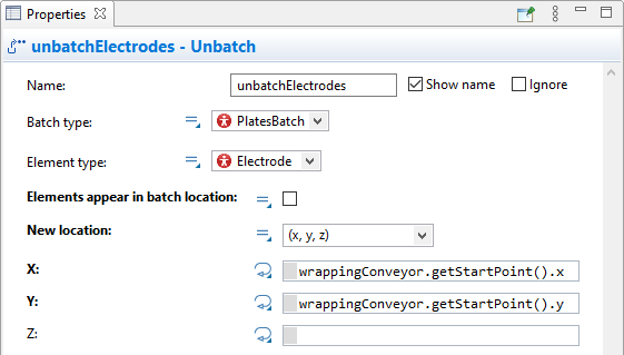 wrappingConveyor, therefore we have to add another block to model the movement of the electrodes along the conveyor.
- Add the
 Convey block to the flowchart after the unbatchElectrodes block.
 - Name it wrappingConvey.
- Adjust its properties as follows:
- Source conveyor:
 wrappingConveyor.
 - Target conveyor: wrappingConveyor.
- Select the Leave conveyor on exit check box
The wrapped electrodes will change their color once again. To model this, we will use the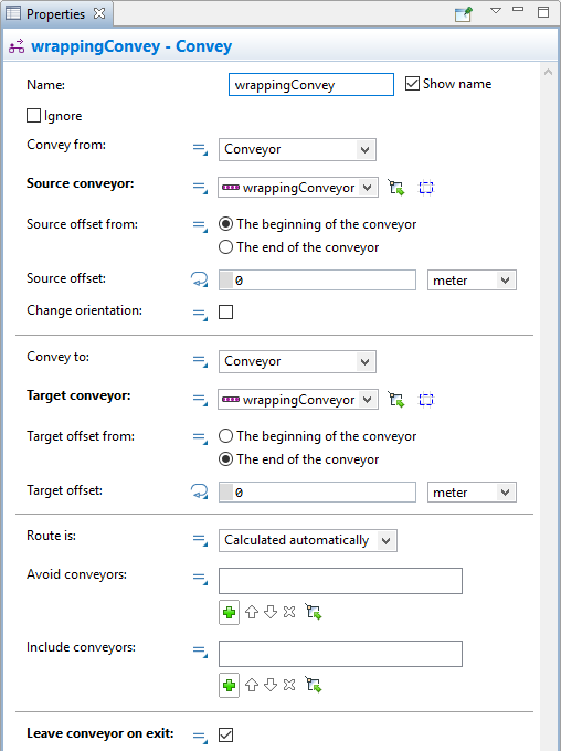 wrappingStation.
- Source conveyor:
- Open the
wrappingStation properties and expand the Actions section.
- In the On process finished field type the following code: agent.color = white;
- Run the model and observe the electrodes wrapping process.
First of all, we need a new material item type to represent the assembled electrode groups.
Create a new material item type
- Drag the
Material item type element from the
Material Handling Library palette to the
Main graphical diagram.
- In the New agent wizard specify the Agent type name: BatteryBlock and click Finish.
- In the
BatteryBlock graphical editor select the Scale element and set the Ruler length corresponds to: 1 meter.
- Drag the Lead Acid Battery Plate Group 3D object from the Manufacturing section of the
3D Objects palette to the
BatteryBlock graphical diagram and place it at the axis origin.
- In the Auto scale 3D object dialog that appears, click Yes.
-
While holding down Ctrl (macOS: Cmd), drag the 3D object twice to make two copies and arrange them as shown in the figure below:
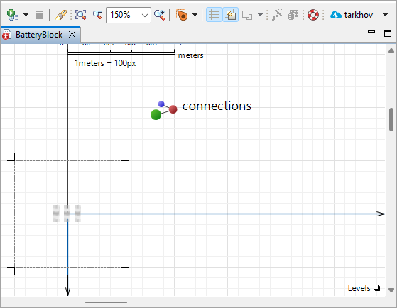 The figure is zoomed; the actual scale is less than 150%.
To describe the assembly process in the flowchart diagram, we will use the Assembler block.
Add the groups assembly logic
- Drag the
 Assembler block from the
Process Modeling Library palette to the
Main graphical diagram and add it to the chart before the sink block.
Assembler block from the
Process Modeling Library palette to the
Main graphical diagram and add it to the chart before the sink block. - Make sure that the connection is established with the uppermost in port of the assembler block.
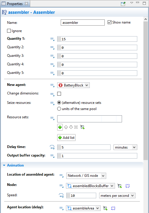
- In the properties of the assembler block specify the following parameters:
- The number of incoming agents needed to assemble a single new agent in the Quantity 1: 15
- Quantity 2: 0
- New agent:
BatteryBlock
- Time needed to create a single block of electrodes in the Delay time: 5 minutes
- Output buffer capacity: 1
- Location of assembled agent: Network/GIS node
- Node:
assembledBlocksBuffer
- The area where the assembly process takes place in the Agent location (delay):
assembleArea
If you run the model now, AnyLogic will warn you that the agents pass through the assembler block without delay, since you haven’t specified the resources that are required to perform the assembly.
Add the resources
- Drag the
Resource Type element from the
Process Modeling Library palette to the
Main graphical diagram.
- In the New agent wizard specify the Agent type name: Operator and click Next.
- In the displayed list of the 3D models expand the People section and select Worker. Click Finish.
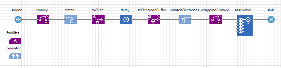
- Now, switch to the
Main graphical diagram and drag the
 Point Node element from the
Space Markup palette.
Point Node element from the
Space Markup palette. - Place it on the layout next to the
assembleArea as displayed in the image below:
- Name the node operatorLocation. During the model run our worker will be located here.
- In the node’s properties specify Visible: no.
- Drag the
 ResourcePool block from the
Process Modeling Library palette to the
Main graphical diagram and name it operator.
ResourcePool block from the
Process Modeling Library palette to the
Main graphical diagram and name it operator.
- Go to the block’s properties and select
Operator in the New resource unit parameter.
- Next, in the Home location (nodes) property specify the
 operatorLocation.
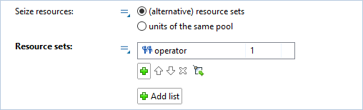
 - Finally, go to the assembler block’s properties and select the operator in the Resource sets: by clicking
 button:
- Run the model!
-
How can we improve this article?
-