

The Decision block is the simplest way to route the algorithm flow. The block has two exit branches — true and false. You can define any sequence of actions for either of the two branches using other action chart blocks. When the control reaches the “decision” block, it decides which branch to take. If the condition defined for this “decision” block is met (that is, it evaluates to true), true branch is taken. Otherwise, false branch is taken.
To activate the Actionchart palette
-
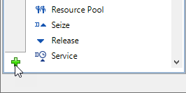
Navigate to the bottom of the Palette view and click the button.
-
Select the Actionchart item from the displayed menu of available palettes and click it.
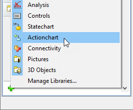
- Actionchart palette will appear in the Palette view.
To insert a “decision” block into an action chart
-
Drag the
 Decision element from the
  Actionchart palette onto the diagram of agent. While moving the mouse over the graphical editor you will see insertion points of action chart(s) indicated with little blue circles. Release the mouse button over the insertion point where you want to place the block. New “decision” block will be inserted into this place.
- Go to the Properties view. Specify the condition in the Condition field. Condition is Java expression that produces a boolean result. You will see it shown in the block on the diagram.
-
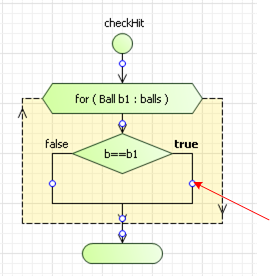
Insert action chart blocks defining the required action you want to execute in any branch of this “decision” block. Place block into insertion point of the corresponding branch as shown in the figure below:
To invert true and false branches
- If you want to invert actions that will be taken on true and false, right-click (macOS: Ctrl + click) the “decision” block in the graphical editor and choose Invert the decision from the popup menu.
By default, the “decision” branches are located in the following way: true branch exits from the right corner of the block, and false — from the left one. However, you can adjust the layout of the branches.
To adjust the “decision” branches layout
-
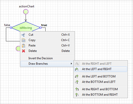
Right-click (macOS: Ctrl + click) the “decision” block in the graphical editor and choose the option you need from the Draw branches submenu of the popup menu. The choices have intuitive names and descriptive figures. Emphasized branch on these figures denotes true branch:
- General
-
Condition — Boolean condition of this “decision” element. When the control reaches the “decision” block, it decides which branch to take. If the condition defined for this “decision” block is met (that is, it evaluates to true), true branch is taken. Otherwise, false branch is taken.
- Advanced
-
Name — The name of the element.
Label — You can add here some comments, explaining the meaning of this “decision” element. The comments will be shown inside the block instead of the “decision” code.
Fill color — Sets the fill color for the element. Click inside the control and choose a color from the set of most used ones, or choose some custom color using the Colors dialog box.
-
How can we improve this article?
-