

The graphical editor does not have any borders — there is virtually infinite canvas at your hands. However, when you run the model the presentation window of the fixed size is displayed, so that only some part of the presentation is shown there. So, it is important to understand, what gets into this visible area.
Graphical editor has coordinates. When you work in the graphical editor, the current mouse coordinates are displayed in AnyLogic status bar (see the figure below).
When you open the graphical diagram, the axis origin (0, 0) is located in the upper left corner of the diagram. You can see dark grid lines indicating coordinate axes. Arrow at the end of the axis shows the axis direction — the direction of the coordinates growth. The X-axis is directed to the right, and the Y-axis is directed down (not up, please pay your attention!). The Z-axis is directed towards the viewer.
Axes define left and upper borders of the visible area of the diagram. The lower and right borders of the visible area are defined by the settings of the model frame and are shared between all agents and experiments of the model.
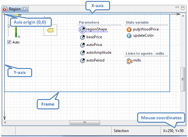 Agent type diagram opened in the graphical editor
-
How can we improve this article?
-