

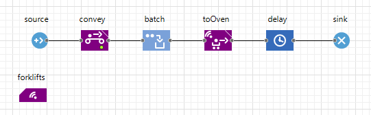
After the electrodes have been collected into batches, they must be moved to the curing oven, where the moisture is removed from them, and then to the next production stage, where the electrodes are wrapped in special envelopes. Let’s start simulating this process with adding the forklifts to our model.
To model the forklifts, we will use transporters — a specific agent type defined by the TransporterFleet block of the Material Handling Library. Transporters can be of different navigation types: either path-guided or free-space.
We will use the transporters with free space navigation type. During movement, they detect their surroundings (defined by markup elements, such as walls, conveyors, etc.) and avoid the obstacles and each other. Each transporter uses an automatically calculated route to reach the destination point in the most efficient manner, i.e. its route will be as short as possible.
Create the forklifts
- Drag the
 Transporter type element to the
Main graphical diagram.
Transporter type element to the
Main graphical diagram. - In the New agent wizard, specify Agent type name: Forklift. Click Next.
-
On the next page of the wizard, open the Warehouses and Container terminals section and select the Fork Lift Truck shape.
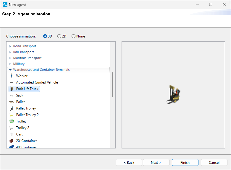
- Click Finish.
-
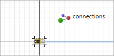
AnyLogic will automatically open the diagram of the newly created agent and place the selected 3D shape onto the diagram. Adjust the position of the shape slightly so that it is closer to the origin of the coordinates, as shown in the figure below:
- In the Dimensions and movement section of the
Forklift agent’s properties, specify the following:
- Length: 2 meters
- Width: 1.3 meter
- Height: 1.5 meter
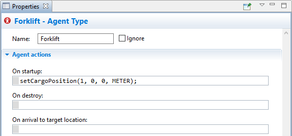
- In the On startup field of the Agent actions section type the following code to set the position of the transported object in relation to the forklift’s center point: setCargoPosition(1, 0, 0, METER);
Draw the forklifts' home location
- Drag the
 Rectangular Node from the
 Space Markup palette to the
Main graphical editor.
Space Markup palette to the
Main graphical editor. - Name it forkliftsHomeLocation.
- In the properties of the node, select Visible: no.
-
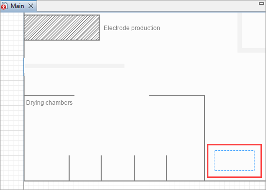
Resize and position the node as shown in the figure below:
-
For the forklifts to always return to the same positions in the node, we need to mark these positions with attractors.
In the properties of the node, click Attractors button. The Attractors dialog appears; specify the Number of attractors: 2.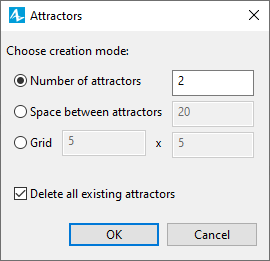
- Click OK to add the attractors inside the node.
- Press and hold Shift, then click both attractors to open the properties for multiple elements.
- From the Orientation drop-down list, select -90.0. The attractors should now face up.
-
If necessary, adjust the position of the attractors using the figure below as a reference:
Draw the curing oven
- Drag the
Rectangular Node from the
Space Markup palette to the
Main graphical editor.
- Name it curingOven.
- In the properties of the node select the option Visible: no.
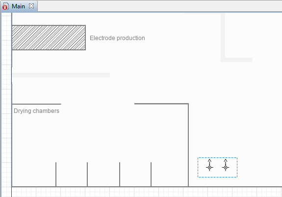
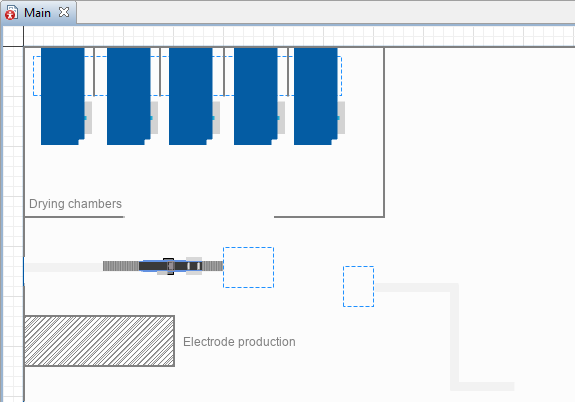
- Adjust the size and placement of the node as displayed in the image below.
- In the node’s properties click the Attractors button to specify the placement of agents in the node.
- In the displayed dialog window select the Grid option and set the values to 5 x 1. Drag the attractors to adjust their placement.
Add the 3D animation
- Go to the
 3D Objects palette in the
 Palette view.
 - Drag the Drying Chamber 3D object from the Manufacturing section of the palette to the
Main graphical diagram and place it over the attractor in the
curingOven node.
- In the displayed Auto scale 3D object dialog window click the Yes button.
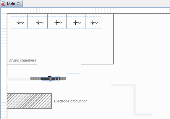
- Adjust the placement of the figure until it is located inside the walls of our layout and fully covers the attractor.
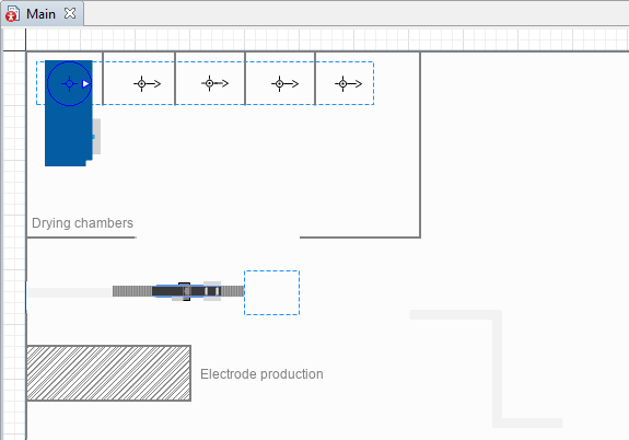
- Ctrl + drag (macOS: Cmd + drag) the 3D figure to the next attractor. It will create a copy of the 3D figure there. Repeat the process until there are 5 curing ovens on the layout.
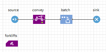
Now that we have created the agent type to represent forklifts and drawn their source and target locations, let’s add the corresponding logic to our model.
Add the forklifts logic
- Open the
 Material Handling Library palette and drag the
 TransporterFleet block to the
Main graphical diagram.
TransporterFleet block to the
Main graphical diagram. - Name it forklifts.
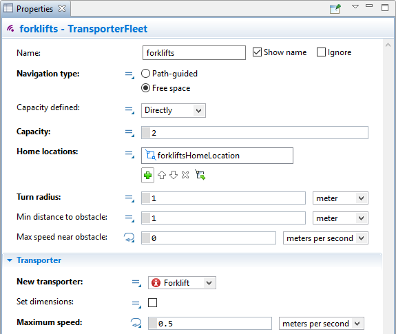
- In the forklifts properties specify the following:
- In the Navigation type parameter select the Free space option. Now the forklifts we want to model will move independently, navigating the obstacles on the factory floor on their own.
- Adjust the fleet’s Capacity: 2. Two forklifts will be enough to transfer the electrodes between the buffer area and the curing oven.
- Select the
forkliftsHomeLocation node as the Home locations for the fleet.
- Set the Turn radius of the forklift truck to 1 meter.
- In the New transporter parameter select the
Forklift.
- Set the Maximum speed of the forklifts to 0.5 meters per second.
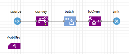
- Drag the
 MoveByTransporter block from the
Material Handling Library palette to the
Main graphical diagram and place it in the flowchart after the batch block.
MoveByTransporter block from the
Material Handling Library palette to the
Main graphical diagram and place it in the flowchart after the batch block.
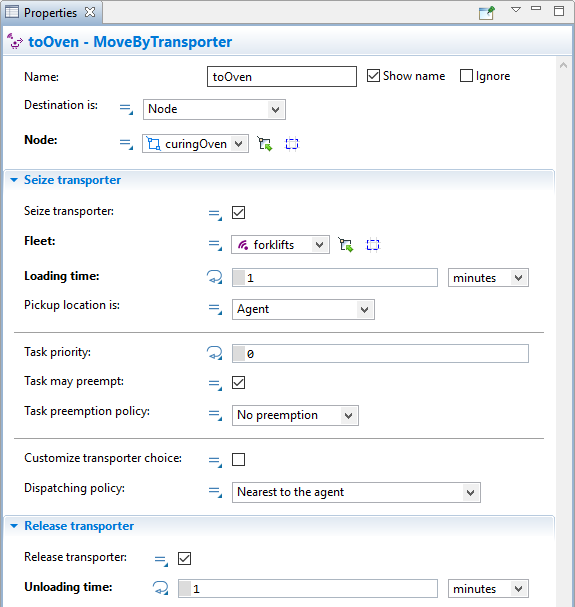
- In the block’s properties specify the following:
- Name: toOven
- Destination is: Node
- Node:
curingOven
- Fleet:
 forklifts
 - Loading time: 1 minute
- Unloading time: 1 minute
Model the curing process
After the electrodes are delivered to the curing oven, they must spend some time inside until the moisture is removed from them. In real life the curing process takes a long time, something between 12 and 24 hours. For the purposes of our tutorial, we will significantly decrease this time.
- Drag the
 Delay block from the
 Process Modeling Library palette to the
Main graphical diagram and place it in the flowchart after the toOven block.
Process Modeling Library palette to the
Main graphical diagram and place it in the flowchart after the toOven block.
- In the block’s properties set the Delay time to 2 minutes.
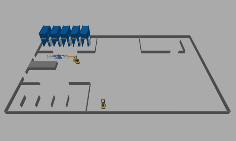
- Run the model to see how the forklifts transfer the batches of electrodes.
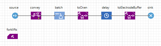
Model the transfer to the pre-wrapping buffer area
- First, draw a rectangular node on the layout according to the image below.
- Name it preassembleElectrodeBuffer. This node will represent the place where the cured electrodes must be transferred.
- In the node’s properties select Visible: no.
- Set the Locations layout to Arranged.
- Add another
MoveByTransporter block to the flowchart and place it after the delay block. Name the block toElectrodeBuffer.
- In the toElectrodeBuffer block’s properties specify the following:
- Node:
preassembleElectrodeBuffer.
- Fleet: forklifts.
- Loading time: 0.5 minutes.
- Unloading time: 0.5 minutes.
- Node:
- Run the model and observe the forklifts navigating the production floor in free space mode.
-
How can we improve this article?
-