

Agents can move between the blocks of your flowchart only if the ports of these blocks are joined via connectors — paths that agents use to flow through the model.
There are output and input ports in the blocks. You may only connect outputs to inputs, otherwise you will get a runtime error.
You can connect multiple output ports to one input port and multiple input ports to one output port. The only exception from this rule is the Fluid Library. For more information on the Fluid Library port connections, refer to the corresponding Fluid Library ports article.
In case multiple output ports are connected to one input port and more than one block wants to pass over an agent, the fair choice of agent is provided by a kind of round-robin algorithm implemented in the input port.
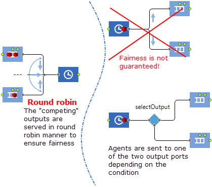
If one output port is connected to several input ports, it will choose the “first in some internal queue” port among those that are ready to accept the agent. More precisely, the output port will rely on the choice of AnyLogic engine among several simultaneous events. Fairness is not guaranteed in this case and such connection is therefore prohibited: it will cause an error at model runtime. To have full control over the agent distribution, use the SelectOutput blocks or custom agent routing implemented via blocks that take agents out of the process flow or put them into the flowchart. See the list of library specific blocks below:
| AnyLogic library | Blocks |
|---|---|
|
Process Modeling Library Material Handling Library |
|
| Pedestrian Library |
 PedEnter PedEnter PedExit PedExit
|
| Rail Library |
 TrainEnter TrainEnter TrainExit TrainExit
|
| Road Traffic Library |
 CarEnter CarEnter CarExit CarExit
|
| Fluid Library |
 FluidEnter FluidEnter FluidExit FluidExit
|
To connect two ports automatically
This option is available by default. To disable it, go to Tools > Preferences > Graphical editor and deselect Connect automatically, when ports are close enough option.
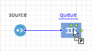
- Drag a block from the Palette view and hover it next to the block where you want to establish the connection.
-
When you see a connector appear between the ports of these two blocks, drop the block on the graphical editor.
To draw a connector between two blocks manually
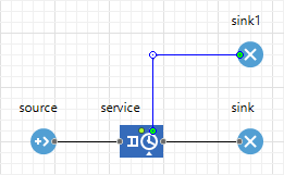
- Double-click the port of the block where you want to start drawing the connector.
- If you need to draw a straight line between two blocks, simply click once on the port of the block where you want the connector to end.
-
If you need to draw a connector with a complex shape, click the graphical editor to place the first salient point. Keep placing these points until you achieve the intended shape of the connector and place the last click on the port of the block where you want the connector to end.
-
How can we improve this article?
-