


The Arc is a three-dimensional shape you can use in your model presentations.
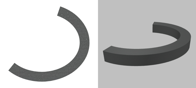
The figure below shows an arc that can be displayed both in 2D and 3D at runtime. The base of the arc is drawn in the graphical editor, while the height is specified in the Z-Height property of the shape.
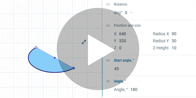
The form of the arc is defined by two properties: Start angle and Angle.
- Start angle defines the position of the starting point of the arc relative to the arc origin point (the center of the base circle or oval).
- Angle defines the position of the ending point of the arc relative to the starting point of the arc.
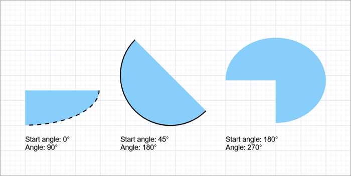
Both angles are calculated in degrees, clockwise, starting at 3 o’clock.
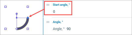 A round arc starting at 0°, with a 90° angle.
The figure below shows arcs with different angle settings:
To draw an arc
- Drag the
 Arc element from the
  Presentation palette into the graphical editor.
 - Alternatively, click the Arc element in the palette and then click a point in the graphical editor. That point will become the origin point (the center of the base shape) for the new arc.
- By default, the base of the arc is a
 Circle. To change that, go to the Appearance section of the element’s properties, then click the
  Oval button in Type.
 - Back in the graphical editor, using the handles, you can resize the arc with a circle base and change both the size and curvature of an arc with an oval base.
- In the Position and size section of the properties, you can:
- set the arc height in the Z-Height field (in pixels, 10 by default)
- change the arc length by adjusting the Start angle and Angle values
- set the change in elevation between the starting and ending point in the dZ edit box (in pixels, 0 by default)
- General
-
Name — The name of the shape. It is used to identify and access the shape from code.
Show name — If selected, the shape’s name is displayed on a presentation diagram.
Lock — If selected, the shape is locked: it will not respond to any mouse actions during the model development time. To select it, click its icon in the elements view. This is frequently needed when you use a shape as a background image for your animation and you want to prevent editing this shape while drawing other shapes over it.
Ignore — If selected, the shape is excluded from the model.
- Appearance
-
Type — The shape of the arc base:
Circle — arc base radiuses are all equal
Oval — arc base radii can vary
Fill color — The color of the arc fill. Click inside the control and select the required color using the colors dialog box. Select no color if you do not want the area inside the curve to be filled.
You can also specify a dynamic expression defining the shape fill color. It should return an instance of the Color Java class. If the expression returns null, the shape is not filled.Line color — The color of the arc line. Click inside the control and select the required color or texture using the Colors dialog box. If you do not want the arc line to be visible, select no color.
You can specify an expression that will be re-evaluated dynamically. It should return an instance of the Color Java class.Line width — The width of the arc line. Select width using the buttons or enter the value in pixels in the field to the right. Enter 0 if you don’t want a line to be drawn.
Line style — The style of the line. Using the buttons, select whether the line will be solid, dashed, or dotted.
- Position and size
-
Level — The level to which this element belongs.
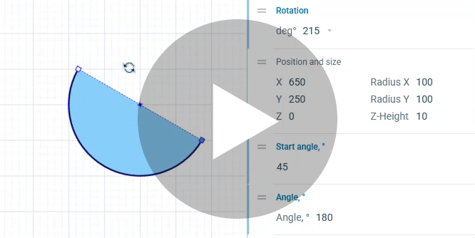
Rotation — The arc rotation angle in the XY plane.
Position and size
X — The X-coordinate of the arc origin point (the center of its base).
Y — The Y-coordinate of the arc origin point (the center of its base).
Z — The Z-coordinate of the arc origin point (the center of its base).
Radius X — The X-axis radius of the arc (in pixels).
Radius Y — [Enabled if Type: Oval] The Y-axis radius of the arc (in pixels).
Z-Height — The Z-axis height of the arc (in pixels).Start angle, ° — Defines the position of the starting point of the arc line (marked with a blue square). Calculated clockwise, relative to the arc origin point (at the same Y-axis value if the shape is not rotated).
Angle, ° — Defines the position of the ending point of the arc (marked with a white square). Calculated clockwise, relative to the starting point of the arc.
dZ — The Z-offset of the ending point of the arc relative to its starting point.
Scale — Here you can specify the expressions returning the scale factors for the shape along the X, Y and Z axes.
- Actions
-
 Add — Here you can specify a trigger that will start code execution.
On click — Here you can enter Java code that will be called each time a user clicks on the shape at model runtime. If there are several shapes overlapping at the click point, the click will interact with the topmost shape only.
Local variables:
self — the element itself
clickx — x-coordinate of the click relative to the shape coordinates
clicky — y-coordinate of the click relative to the shape coordinates
- Visibility and presentation
-
Visible — Here you specify whether the shape is visible in the animation at model runtime. If you expect visibility to change dynamically or to depend on some conditions, you can specify the expression defining the shape visibility. This expression will be dynamically re-evaluated at model runtime. It should return a boolean value. The shape is visible when the specified expression evaluates to true, and not visible otherwise.
Show in — Here you can select whether this shape is displayed in both 2D and 3D animation, in 2D only, or in 3D only.
Agent presentation — If selected, the shape is included in the agent presentation. This means that if the agent hosting this shape is embedded in another agent, the shape will remain visible.
Agent icon — If selected, the shape is considered a part of the agent icon. Please note that icon shapes are not shown in 3D animation.
- Expert
-
Replication — The replication factor of the shape. Here you specify how many copies of the shape will be created. If you leave this field empty, only one shape will be created.
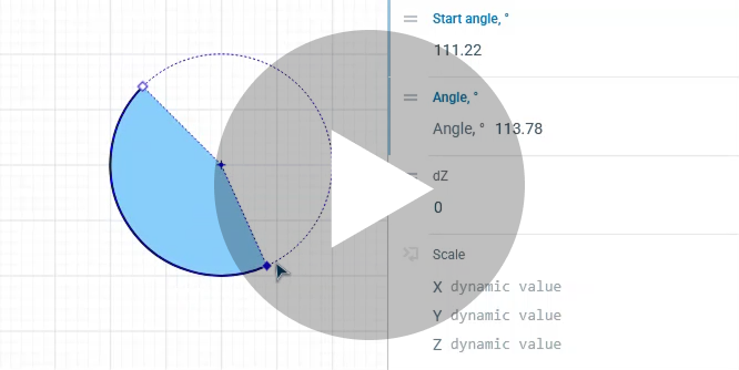
Press the play button to see the animations.
To change the arc length
- Move the starting and/or ending points of the arc by dragging the handles on the arc line: the blue diamond for the starting point, the white diamond for the ending point.
To change the arc curvature
- In the Appearance section of the element properties, select the type Oval using the corresponding button.
- Resize the shape in any direction using the white square handles.
To rotate the arc
- Next to the origin point (the center of the base circle or oval), you can see the round rotation handle. Hover over it, the cursor should turn into
 .
. - Click the handle and, holding the mouse button, move the mouse in the required direction.
You can dynamically modify shape properties at model runtime using the following API.
- Location
-
Function Description double getX()
double getY()
double getZ()Returns the X-, Y-, or Z-coordinate of the arc origin point (the center of its base shape). void setX(double x)
void setY(double y)
void setZ(double z)Sets the X-, Y-, or Z-coordinate of the arc origin point.
x — the new X-coordinate value
y — the new Y-coordinate value
z — the new Z-coordinate valuevoid setPos(double x, double y) Sets new coordinates for the arc origin point.
x — the new X-coordinate value
y — the new Y-coordinate valuevoid setPos(double x, double y, double z) Sets new coordinates for the arc origin point.
x — the new X-coordinate value
y — the new Y-coordinate value
z — the new Z-coordinate value - Angles
-
Function Description double getAngleStart() Returns the starting angle of the arc (0 means 3 o’clock) in radians, clockwise. void setAngleStart(double angleStart) Sets the starting angle of the arc (0 means 3 o’clock) in radians, clockwise.
angleStart — the starting angle of the arcdouble getAngle() Returns the angular extent of the arc in radians, clockwise. void setAngle(double angle) Sets the angular extent of the arc in radians, clockwise.
angle — the “vertical” radius of the arc, in pixels - Radiuses
-
Function Description double getRadiusX() Returns the “horizontal” radius of the arc, in pixels. double getRadiusY() Returns the “vertical” radius of the arc, in pixels. void setRadiusX(double radiusX) Sets the “horizontal” radius of the arc, in pixels.
radiusX — the “horizontal” radius of the arc, in pixelsvoid setRadiusY(double radiusY) Sets the “vertical” radius of the arc, in pixels.
radiusY — the “vertical” radius of the arc, in pixelsvoid setRadius(double radius) Sets both radii of the arc to the same given value, making it circular.
radius — the circular arc radius - Scaling
-
Function Description double getScaleX()
double getScaleY()
double getScaleZ()Returns the scale of the shape along the X-, Y-, or Z-axis. void setScaleX(double sx)
void setScaleY(double sy)
void setScaleZ(double sz)Sets the scale of the shape along the X-, Y-, or Z-axis.
sx — the new X-axis scale factor*
sy — the new Y-axis scale factor
sz — the new Z-axis scale factorvoid setScale(double sx, double sy) Sets the scales of the shape along both axes.
sx — the new X-axis scale factor
sy — the new Y-axis scale factorvoid setScale(double s) Sets the same scale for both X- and Y-axis.
s — the new scale factorSet the scale to 1 to keep the original size. - Rotation
-
Function Description double getRotation() Returns the rotation of the shape in radians, clockwise. void setRotation(double r) Sets the rotation of the shape.
r — the new rotation value, in radians - Visibility
-
Function Description boolean isVisible() Checks the visibility of the shape. If the shape is visible, returns true, otherwise false. void setVisible(boolean v) Sets the visibility of the shape.
v — visibility: if true, the shape is visible, if false, not visible - Fill color
-
Function Description Color getFillColor() Returns the fill color of the shape; null if the shape has no fill color or has a textured fill (to get the texture, use getFillTexture() instead). Texture getFillTexture() Returns the fill texture if the shape is filled with one. void setFillColor(Color fillColor) Sets the fill color of the shape.
fillColor — the new fill color; if null, the shape is not filledvoid setFillColor(Paint fillColor) Sets the fill color or texture for the shape.
fillColor — the new fill color or texture; if null, the shape is not filled - Outline
-
Function Description Color getLineColor() Returns the line color of the shape; null if the shape line has no color or the line is filled with a texture (to get the texture, use getLineTexture() instead). Texture getLineTexture() Returns the line texture if the shape line is filled with one. void setLineColor(Color lineColor) Sets the line color for the shape.
lineColor — the new line color; if null, the shape line is not drawnvoid setLineColor(Paint lineColor) Sets the line color or texture for the shape.
lineColor — the new line color or texture; if null, the shape line is not drawndouble getLineWidth() Returns the width of the shape line. void setLineWidth(double width) Sets the width of the shape line, 0 means thinnest possible.
width — the new width of the shape lineLineStyle getLineStyle() Returns the style of the shape line.
Valid values:
LINE_STYLE_SOLID — the line is drawn solid
LINE_STYLE_DOTTED — the line is drawn dotted
LINE_STYLE_DASHED — the line is drawn dashedvoid setLineStyle(LineStyle lineStyle) Sets the style of the shape line.
style — the new style of the shape line
Valid values:
LINE_STYLE_SOLID — the line is drawn solid
LINE_STYLE_DOTTED — the line is drawn dotted
LINE_STYLE_DASHED — the line is drawn dashed - Draw mode (2D / 3D)
-
Function Description ShapeDrawMode getDrawMode() Returns the drawing mode of the shape (dimension-wise).
Valid values:
SHAPE_DRAW_2D3D — show the shape in both 2D and 3D animation
SHAPE_DRAW_2D — show the shape in 2D animation only
SHAPE_DRAW_3D — show the shape in 3D animation onlyvoid setDrawMode(ShapeDrawMode drawMode) Sets the drawing mode of the shape (dimension-wise). This method can be called only once and only for the shapes created using the constructor without arguments. The call which changes the set draw mode will throw an error.drawMode — the new draw mode for the shape
Valid values:
SHAPE_DRAW_2D3D — show the shape in both 2D and 3D animation
SHAPE_DRAW_2D — show the shape in 2D animation only
SHAPE_DRAW_3D — show the shape in 3D animation only - Group
-
Function Description ShapeGroup getGroup() Returns the group containing this shape. - Level
-
Function Description Level getLevel() Returns the level where this shape is located. - Points inside the shape
-
Function Description boolean contains(double px, double py) Test if the shape contains the point with the given coordinates (relative to this shape’s container, i.e. in the same system with the coordinates of this shape, x and y). Returns true if the shape contains the point with the given coordinates.
px — the X-coordinate relative to this shape’s container
py — the Y-coordinate relative to this shape’s containerPoint randomPointInside() Returns a random point inside the shape area.
This function utilizes Random Number Generator of the Presentable object containing this shape.
Will throw an exception if the shape has been created from code and has not been added to any group. In this case, use randomPointInside(Random rng).Point randomPointInside(java.util.Random rng) Returns a random point inside the shape area. This function utilizes the given Random Number Generator.
rng — the random number generator
-
How can we improve this article?
-