


The camera determines which part of the presentation will be displayed in the 3D window. It “shoots” the picture that is “shown” in the 3D animation window (similar to a display on an operator’s console).
If you want certain presentation shapes to be shown in the 3D window on model startup, we recommend defining the onlooker’s location and eye direction when using the camera rather than navigating to the required shapes each time the model runs.
You can define several cameras that are directed either at different parts of the 3D scene, or at the same objects from different points. You can easily switch between these cameras at runtime.
The camera can move during model runtime, and the 3D window can be set to follow the camera and show the current picture it shoots. This feature is useful if your model includes a moving object that you want to keep an eye on.
Demo model: Multiple 3D Windows and Cameras Open the model page in AnyLogic Cloud. There you can run the model or download it (by clicking Model source files). Demo model: Multiple 3D Windows and CamerasOpen the model in your AnyLogic desktop installation.To add a camera
-
Drag the
 Camera element from the 3D section of the
  Presentation palette into the graphical editor. You will see the camera icon in the graphical editor:
- Direct the camera at the presentation shapes that you want to see in the 3D window at model runtime (positioning is described below in details).
- Now you can set this camera as the camera shooting the picture for the 3D window. Select the 3D window and select this camera in its Camera property. If you plan to move your camera at model runtime, and you want your 3D window to follow the camera and show the picture that currently gets into its focus, choose the Follow camera option.
- General
-
Name — The name of the camera. It is used to identify and access the camera from code.
Show name — If selected, the name of the camera will be displayed on the presentation diagram.
Ignore — If selected, the camera will be excluded from the model.
- Position
-
Level — The level to which this camera belongs.
X — The x-coordinate of the center of the camera.
Y — The y-coordinate of the center of the camera.
Z — The z-coordinate of the center of the camera.
Rotation X — The angle at which the camera intersects the YZ plane, starting from the inverted Y axis, clockwise, in degrees.
Rotation Z — The angle at which the camera intersects the XY plane, starting from the inverted Y axis, clockwise, in degrees.
- Visibility and presentation
-
Show in — Select whether the element is displayed in both 2D and 3D animation, 2D only, or 3D only. For the Camera element specifically, 3D is always selected and active.
When adding a camera onto diagram of your agent, you should direct your camera towards the shapes you want to be “shot” by this camera.
To direct the camera at the required presentation shapes
-
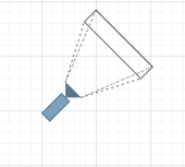
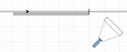
Place the camera near the shapes you want to see in the 3D window. For best results, place the camera at the distance, as shown in the figure below:
-
Select the camera in the graphical editor. A blue circle will appear around the camera icon, along with an arrow indicating the current viewing direction in the XY plane.
To rotate the camera horizontally (around the Z axis), hover over the arrow. The cursor will change to indicate that you can drag it. Drag the arrow around the circle to rotate the camera clockwise or counterclockwise.
To adjust the vertical angle (Rotation X), drag the tip of the arrow closer to or farther from the center of the camera icon. This changes the camera’s tilt. By default, the camera is positioned above the scene (typically at Z = 100), so adjusting this changes how steeply the camera looks downward. - Start the model. You can fine-tune the camera’s view at runtime: zoom in or out, pan the view, or rotate the camera interactively. When you are satisfied with the position, right-click (macOS: Ctrl + click) inside the animation window and select Copy camera location to save the current settings to the clipboard.
- To apply these settings to your camera, return to the graphical editor. Right-click the camera and select Paste coordinates from clipboard from the context menu. The camera will instantly update its position and orientation based on the copied settings.
- Location
-
Function Description double getX() Returns the X-coordinate of the camera. double getY() Returns the Y-coordinate of the camera. double getZ() Returns the Z-coordinate of the camera. void setX(double x) Sets x as the new X-coordinate of the camera. void setY(double y) Sets y as the new Y-coordinate of the camera. void setZ(double z) Sets z as the new Z-coordinate of the camera. void setPos(double x, double y, double z) Sets new coordinates for the camera.
x — the new value of X-coordinate
y — the new value of Y-coordinate
z — the new value of Z-coordinate - Rotation
-
Function Description double getRotationX() Returns the rotation of the camera around X axis (CW, from Y to Z). Zero rotation value corresponds to horizontal orientation of the camera (parallel with XY-plane). double getRotationZ() Returns the rotation of the camera in radians around Z axis (CW from X to Y). void setRotationX(double rotationX) Sets the rotation of the camera around X-axis (CW, from Y to Z). Zero rotation value corresponds to horizontal orientation of the camera (parallel with XY-plane).
rotationX — the new value of rotation around X-axis (CW, from Y to Z), in radians.void setRotationZ(double rotationZ) Sets the rotation of the camera in radians around Z-axis (CW from X to Y).
rotationZ — the new value of rotation in radians around Z-axis (CW from X to Y). - Level
-
Function Description Level getLevel() Returns the level, where this camera is located. - Copying camera position to the clipboard
-
Function Description String copyToClipboard() Copies camera settings to the system clipboard in the format supported by AnyLogic IDE.
To paste the camera settings in the AnyLogic, right-click the camera and select Paste coordinates from clipboard from the context menu.
-
How can we improve this article?
-