


Our model will simulate how the cars are taken to a track, sometimes called a lead or a drill. From there the cars are sent through a series of switches, called a ladder, to the classification tracks.
We want to start with the rail network of this topology:

To create a new model
- Log in to AnyLogic Cloud at https://cloud.anylogic.com.
- Click the My models tab to open the page containing your models.
- Now click + New model to open the Create new model dialog box.
-
In the Create new model dialog box that appears, specify the name of the new model: Hump Yard.

- Finally, click Create.
- In the Models view, locate your newly created model and click it.
- The model properties will appear on the right. There, in the Model time section, set the Model time units: minutes.
Typical rail models use a scale of 2 pixels per meter. Since this is not the default value, it is best to set the correct scale before continuing with the model.
To set the model scale
- Locate the Scale element on the
 Main diagram. By default, it is placed above the coordinate origin, so you might need to scroll upward slightly.
 - Click the Scale element to see its properties in the panel on the right.
-
Set the properties to the following:
Scale is: Specified explicitly
Scale: 2 pixels per meters
Now your model is set up correctly, and the scale of trains and tracks will be rendered as expected. We can start with the topology of the rail yard by drawing the railway tracks.
Let us start with a linear track.
To draw a linear railway track
- Click the
 Railway Track element in the
  Rail palette.
 - Click in the Main diagram to start drawing the track.
- Double-click where you want to place the end point of the track to finish drawing.
In the track properties, enter the Name: trackEntry. Trains will appear on this track. We will give meaningful names only to the tracks that will be referenced by the flowchart blocks. Other tracks can keep their default names.

The drawn linear track will be used by our train. Let us draw the bypass track that will be used by the locomotive to approach the train from behind to further move it to the hump yard. This track will have a curved shape and its drawing scenario will be different from the one you have followed so far.
To draw a curved bypass track
-
Click the Railway Track element in the Rail palette.
- Then, click the point on the existing track to begin drawing the bypass track. The circle representing a switch will appear automatically.
-
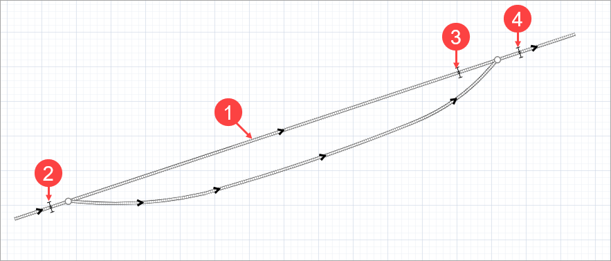
Draw more track segments to get the track shape as shown on the figure below. To add a curved segment, press the left mouse button at the point where the curved segment ends and then move the mouse with the button being pressed. As you drag the mouse, you will see the radius of the curve change. When you are finished, release the mouse button.

-
Double-click to finish drawing the track. You cannot place the end point on the same track where you started drawing ( trackEntry), so double-click near trackEntry.
- Drag the track end point onto trackEntry to create another switch.

To adjust the curved railway track
- Right-click the track you want to edit.
- Select Show guiding lines from the context menu.
- Drag any circle point that lies along the track to move it and reposition the adjacent track segments.
-
Drag a diamond-shaped handle at the end of the dashed guiding line to change the radius of the curved segment.

- The railroad network consists of tracks and switches. Railway switches appear automatically in the shape of a circle when you connect a branch track to an existing railway track. You cannot connect more branch tracks to the same point.
- At each switch, there must be at least two obtuse angles out of three between the ends of the track. The switch determines the routes based on these angles.

To modify the rail yard
The lead track will be divided into tracks each time we create railway switches on it. In our case, we created two switches by connecting a bypass track in two points of the existing track. As a result, the lead track is divided into three tracks with their own names and properties.
Now we will give a meaningful name to the track between the switches and add Position on track shapes to our rail yard.
- Name this track trackArrival, as this is the track where the train arrives.
- Drag the
 Position on track element from the Rail Library palette and place it as shown on picture below. Name it stopLineEntry. It will define the place where trains appear.
 - Add Position on track: stopLineArrival. The train will stop at this point to release the locomotive so that it can continue on its own.
- Add Position on track: stopLineHump. This is where the cars are sorted by type.
Position on track is a space markup shape that is used to define the exact position on the railway track. This is needed when you define:
- The position on the track where the train will appear.
- The position where the train will stop.
In this phase of the Hump Yard tutorial we have created a rail yard.
-
How can we improve this article?
-