


Now we will create another part of the system by adding tellers that are working at the bank. Now some clients will come to see tellers, some — to access the ATM. We can model tellers using delays in the same way as we modeled ATM. However, modeling tellers using resources is much more convenient. Resource is a special unit that can be possessed by an agent. Only one agent can possess a resource at a time; therefore, agents compete for resources.
Create a service
-
Open the
 Process Modeling Library palette and drag the
  Service block onto our
  Main diagram.
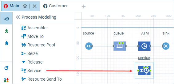 Service seizes resource units for the agent, delays the agent, and releases the seized units.
-
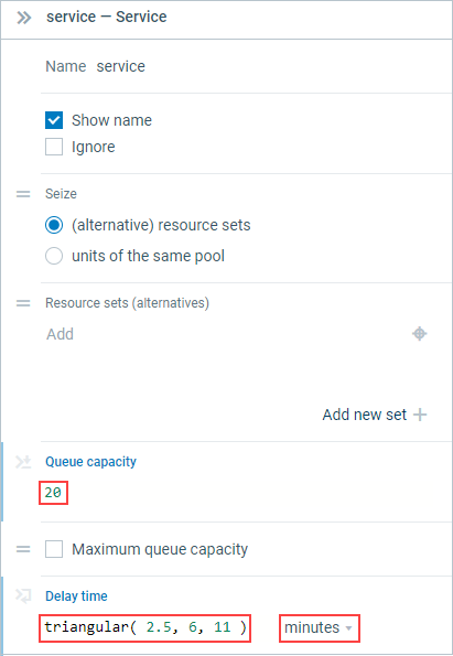
Go to the Properties view of the service block.
-
Modify the block’s properties:
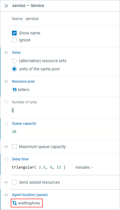
- There is only one queue for all tellers. Set up Queue capacity to 20.
-
We assume that service time is triangularly distributed with the min value of 2.5, average value of 6, and the max value of 11 minutes. Set Delay time to triangular( 2.5, 6, 11 ) and change time units to minutes.
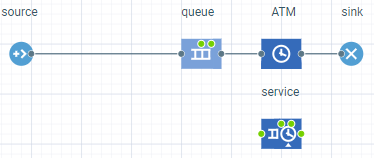
Adjust the process flowchart
-
Move the blocks queue, ATM, and sink to the right to make space for one block between
the source and the queue.
-
Add the
 SelectOutput block in the resulting space. When you place the block on the connector, it will automatically get built in.
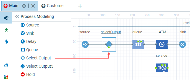 SelectOutput is a decision-making block. Depending on the probability or the user-defined condition, the agent arrives at the block and is forwarded along one of two output ports.
-
Click selectOutput in the flowchart and go to its Properties view. Select the With specified probability [0..1] option for the Select True Output parameter. Set Probability to 0.5.
This probability ensures that the number of customers competing for ATM and teller service will be approximately equal.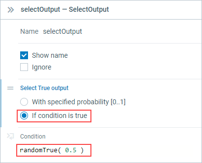
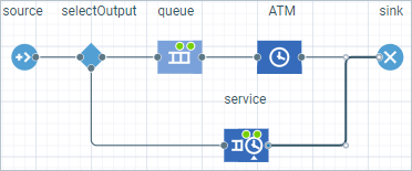
- Connect service with other blocks as shown in the figure:
Add resources for the service
-
Drag the
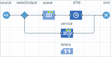
 ResourcePool block onto our Main diagram.
- Place it under service and navigate to its Properties view.
-
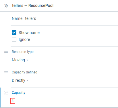
Name the block tellers.
-
Specify that this resource block has only four resource units by setting its Capacity to 4.
-
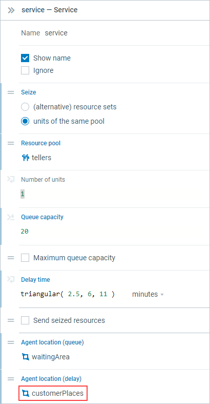
Select service in the flowchart to open its properties. Modify the block’s properties:
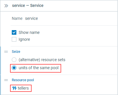
- Set the Seize parameter to units of the same pool.
- Below, click in the Resource pool field and select the resource pool we have previously created.
![]() ResourcePool block is a storage for resource units.
ResourcePool block is a storage for resource units.
![]() ResourcePool block should be connected to resource seizing and releasing block (
ResourcePool block should be connected to resource seizing and releasing block (![]() Service in our case). So we need to modify the properties of the service block.
Service in our case). So we need to modify the properties of the service block.
Now since the model has changed, we need to alter the model animation as well.
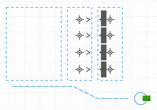
Now we want to draw the area for queuing and a place to get serviced for our clients.
Set up space markup for the queue to tellers
-
This time we will draw a waiting area using a rectangular node. In the
Process Modeling Library palette, click the
 Rectangular Node element to switch to the drawing mode.
-
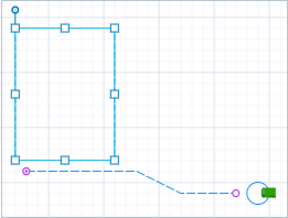
Click in the graphical editor and drag the rectangle without releasing the mouse button. Release when you have a rectangular node of the required form. You can edit its form later as you need.
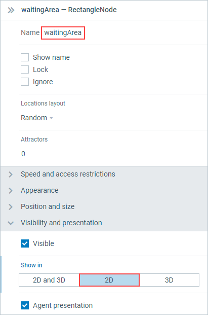
- Name the node waitingArea.
-
In the Visibility and presentation section of the Properties view, switch the Show in control to 2D. This way the markup shape will be invisible in 3D view during animation at model runtime.
- Click the service block in the flowchart and go to its Properties view.
-
Select the waitingArea node in the Agent location (queue) option.
Set up space markup for the customers
The customers need a place to stand somewhere while they are getting serviced by tellers.
-
Draw another Rectangular Node as displayed in the image below. Modify the block's properties:
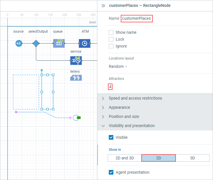
- Name the node customerPlaces
- Switch the Show in control to 2D.
-
In the Attractors field, specify 4. You will see that attractors appeared in the customerPlaces node with an even offset.
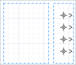
We will use attractors to define the customers that are getting service.
- Now we need to refer to this area in the flowchart. Click the service block in the flowchart and go to its Properties view.
-
Select the customerPlaces node in the Agent location (delay) option.
Set up space markup for the tellers
- Since we have 4 tellers, we will use a rectangular node to draw this service area.
-
Draw another rectangular node as displayed in the image below. Name the node tellerPlaces and in its properties switch the Show in control to 2D.
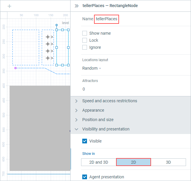
- Create 4 attractors inside the node to specify tellers in the same manner as you have done before.
-
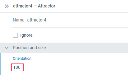
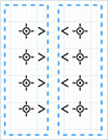
You will see attractors appear in the tellerPlaces node with the even offset, but facing the wrong direction. Select the first attractor and go to the Properties view. In the Position and size section, change the Orientation parameter to 180. Repeat this process for all four attractors.
- Adjust the position of the attractors in the graphical editor if necessary.
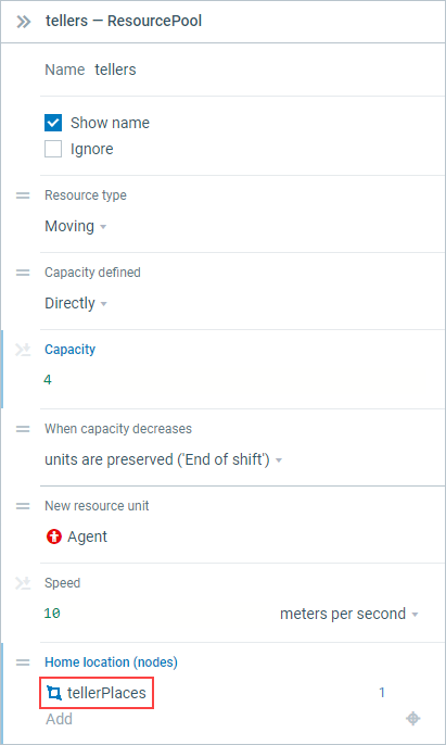
- Click the tellers block in the flowchart and go to its Properties view.
-
Select the tellerPlaces in the Home location (nodes) parameter.
You can run the model now and observe how some customers are getting serviced at the ATM and some go to see tellers.
It is time to add teller 3D objects to our model. We will create a new resource type to animate tellers.
Create a new resource type
-
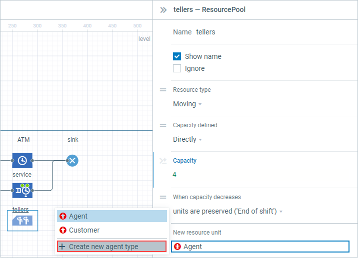
Click the tellers block to open its properties. In the New resource unit field, click the Agent value and choose the
 Create new agent type option.
-
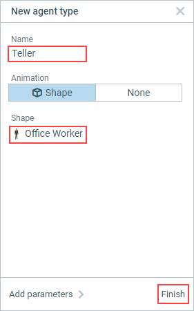
The New agent type wizard will open. Set up the new agent type using the wizard:
- Enter Teller as the Name of the new agent type.
-
Select Office Worker from the list of the 3D figures as a Shape.
-
Click Finish. The new
 Teller agent type will be created.
-
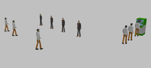
Run the model and observe customers and tellers.
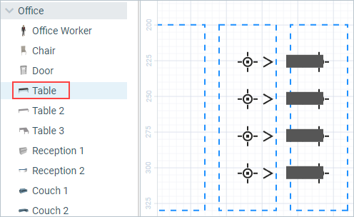
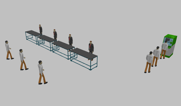
Add tables for the tellers
-
Open the
 3D Objects palette.
-
Drag four Table 3D figures from the Office section of this palette onto the tellerPlaces in the graphical editor.
-
Place the tables over attractors since attractors are the places where the tellers stand.
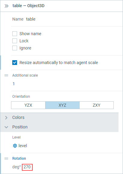
- You can see that their orientation is wrong. Select all tables by clicking them while holding the Shift key and go to the Properties view.
-
In the section Position, change the parameter Rotation to 270 degrees.
-
If necessary, rearrange all eight attractors and four tables so that they are reasonably lined up.
Now you can run the model and observe in 3D how some customers go to the ATM and other get service at the tellers tables.
-
How can we improve this article?
-