


Typically, you add shapes to the model layout by dragging them from the palette into the graphical editor. They appear in a default form, which you can then modify as needed.
Drawing mode gives you more precise control when you create and edit shapes directly in the editor. It is especially useful for elements that involve lines or paths, such as walls (Pedestrian Library), paths (Process Modeling Library), or railway tracks (Rail Library). Not all shapes support the drawing mode, but those that involve geometric drawing usually do. If it is available, the editor automatically switches to it when you select the shape.
To draw a shape
- Click the element on the palette once.
- Click in the graphical editor to begin drawing the shape.
-
Next, click anywhere else to stretch the shape to that point.
Hold down the mouse button and drag as you place the point to make the line curved. - To stop drawing, double-click when you add the terminal point of the shape.
You can exit the drawing mode at any time by pressing Esc. Note that this will remove any segments of the shape you may have previously drawn.
To edit a shape
-
To edit a shape that supports the drawing mode, click it in the editor. Handle points will appear at the angles and terminal points of the shape.
- To realign the shape, drag a point anywhere in the editor. The lines leading to the point will be repositioned relatively to the point.
-
To add a point, double-click anywhere on any segment of the shape, or
Hold Alt (macOS: Option) and click anywhere on a segment. - To make a curved segment, right-click (Mac OS X: Ctrl + click) on any of the shape’s segments and select Make segment curve from the context menu.
- To make a line segment from a curve, right-click (Mac OS X: Ctrl + click) on any of the shape’s segments and select Make segment line from the context menu.
- To remove a segment, double-click one of its points. When you remove a segment from the center of a shape, the two closest points are connected.
-
The context menu also provides several editing options. To access the context menu, right-click the shape in the editor:
-
Copy — Copy the shape to the clipboard.
Press Ctrl + C (macOS: Cmd + C) while the shape is selected to copy the shape without opening the context menu. -
Paste — Paste the shape from the clipboard into the editor.
Press Ctrl + V (macOS: Cmd + V) while the editor is active to paste the shape without opening the context menu. -
Cut — Cut the shape, that is, remove it from the editor and copy it to the clipboard.
Press Ctrl + X (macOS: Cmd + X) while the editor is active to paste the shape without opening the context menu. -
Delete — Delete the shape.
Press Delete while the shape is selected to delete the shape without opening the context menu. -
Add point (visible if you have opened the context menu from the position on the line) — Adds a point.
Double-click the position (or Alt / Option + click) on the line to add a point without opening the context menu. -
Point (visible if you have opened the context menu from one of the handle points) — Expands the list of additional options:
- Smooth point — Makes this point a smooth (curved) angle.
- Corner point — Makes this point a sharp angle.
-
Delete point — Deletes the point.
Double-click the point to delete it without opening the context menu.
Converting a point to smooth or corner also enables the guiding lines; see below. -
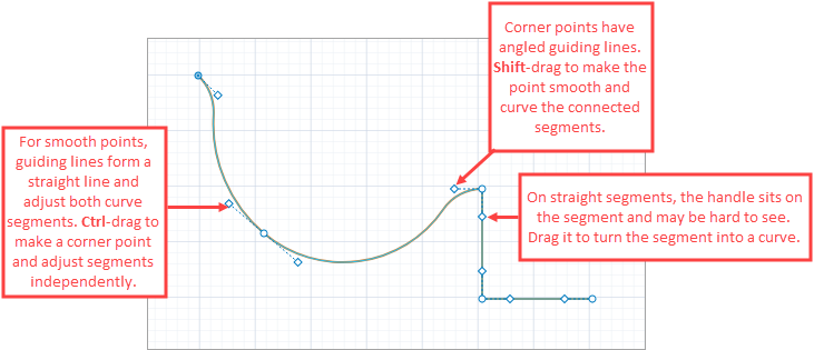
Show/Hide guiding lines — Toggles the visibility of guiding lines on the shape. Guiding lines are used to adjust the curvature of segments connected to a point. When enabled, each point on the shape displays two guiding lines. Terminal points of the shape display only one.
- For smooth points, the guiding lines appear as a straight line with the point in the center.
- For corner points, the guiding lines form an angle. If the connected segment is a straight line, the handle appears directly on the segment..
This option is not available for shapes that do not support curved segments, such as polylines and pipes.To adjust the radius of the curve, click and drag the diamond-shaped handle at the end of a guiding line.
When adjusting the curvature using guiding lines:- If the angle between two guiding lines at a point is 180° (they form a straight line), the point is considered a smooth point. Dragging one handle will adjust the curvature of both connected segments.
- To convert a smooth point to a corner point, hold down Ctrl (macOS: Cmd) while dragging the handle. This enters single-segment mode, where only one side of the shape adjacent to the point is affected.
- To convert a corner point to a smooth point, hold down Shift while dragging the handle. The guiding lines will align at 180° and both connected segments will become curved.
-
Make segment line/curve — Toggles the segment between a line and a curved shape.
This option is not visible for shapes that do not support curved segments, such as polylines and pipes.
-
Append — Click to continue drawing the shape.
After you click the option, the terminal points of the shape will become clickable. Click the terminal point and proceed with drawing as usual. -
Split — Click to activate the shape split mode.
After clicking the option, the points connecting the segments will become visible. Click one of these points to split the shape in two at that point. -
Change direction — Click to change the direction of unidirectional elements (such as pipes).
For bidirectional elements, it affects which terminal point is considered the starting point. The starting point is the one specified by the X, Y, and Z coordinate values in the Position section of the element’s properties.
Press Shift + Enter while the shape is selected to change its direction without opening the context menu. -
Edit shape — Turns shape editing mode on or off.
In editing mode, you can rotate the shape by dragging the handle above its center. You can also resize it using the boundary handles: the segments and points will adjust automatically to the new scale. - Close/Open polyline (visible for polylines) — Click to automatically connect the terminal points of the polyline.
- Close/Open wall (visible for walls) — Click to automatically connect the terminal points of the wall and enclose the space inside the wall (so agents cannot move through it).
-
Select network — Select the entire network (all paths and nodes belonging to this network).
This option is visible only for paths and nodes.
-
Order — Lets you change the display order of shape overlays in the graphical editor for easier visual organization. The following options are available:
- Bring to front — Moves the shape overlay to the top, so it appears above all others at the same X/Y position.
- Bring forward — Moves the overlay one step closer to the front.
- Send backward — Moves the overlay one step toward the back.
- Send to back — Moves the shape overlay to the bottom, so other shapes at the same position appear above it.
This only affects how shapes are displayed in the graphical editor and at runtime. It does not change their X, Y, or Z coordinates in the model logic.
-
Copy — Copy the shape to the clipboard.
-
How can we improve this article?
-