


The 3D Object element enables AnyLogic users to import ready-to-use 3D models created with the help of third-party 3D graphics packets into their models.
3D object supports 3D models created in Collada (DAE) file format.
AnyLogic also provides the ![]() 3D Objects palette containing the set of the most frequently used 3D objects.
3D Objects palette containing the set of the most frequently used 3D objects.
To add a 3D object onto your presentation
- Drag the
 3D Object element from the 3D section of the
  Presentation palette onto the graphical editor.
 - The Open dialog will open automatically. Browse for the required 3D object file in the file system, select it and click Open when finished. You will see the 3D object in the graphical editor.
The 3D object file is displayed in the model’s Resource folder in the Projects view.
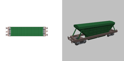
If the 3D object file is not specified for the element, or it cannot find the specified file, the 3D object placeholder is shown:
- General
-
Name — The name of the object. It is used to identify and access the object from code.
Show name — If selected, the object name will be displayed on the presentation diagram.
Lock — If selected, the shape is locked. Locked shapes do not react to mouse clicks — it is impossible to select them in the graphical editor until you unlock them. It is frequently needed when you use your shape as a background image for your animation and you want to prevent editing this shape while drawing other shapes over it.
Ignore — If selected, the object will be excluded from the model.
File — The name of the file containing 3D object that is displayed by this shape. To choose a file, use the Browse... button. The
 button to the right allows to switch between the absolute and relative file paths.
Resize automatically to match agent scale — If selected, the object will be resized automatically to make it correspond to the agent scale. If you change the model scale afterwards, the object will be resized accordingly. In the AnyLogic preferences, you can set resizing to be performed automatically on adding a new 3D object.
Additional scale, % — Here you can adjust the size of the 3D object by the specified percentage. If Resize automatically to match agent scale option is selected, additional scale will be still applied. Another way to resize the object is to select it in the graphical editor and drag the handle located in the bottom right corner of the object.
If you need to specify a fractional value, you should switch the Additional scale, % field to dynamic value editor. Note that the dynamic value that you provide will be applied during the model run, i.e. your changes will not be immediately reflected in the graphical editor.Orientation — Here you can set the orientation of the 3D object in the 3D scene: Top (the object’s upper side), Front, or Side.
- Colors
-
Here you can define colors of the object if they are available for editing.
- Position
-
Level — Level to which this object belongs.
X — X-coordinate of the 3D object.
Y — Y-coordinate of the 3D object.
Z — Z-coordinate of the 3D object.
Rotation — The rotation angle in XY plane (in degrees or radians).
- Actions
 Add — Here you can specify a trigger that will start the code execution.
On click — Here you can type Java code that will be called each time a user clicks on the shape at the model runtime. If there are several shapes overlapping in the click point, the click will interact with the topmost shape only.
Local variables:
self — the element itself.
clickx — X-coordinate of the click relative to the shape coordinates.
clicky — Y-coordinate of the click relative to the shape coordinates.- Visibility and presentation
-
Visible — If selected, the shape is visible on the animation at the model runtime, otherwise not. If you expect visibility to change dynamically or to depend on some conditions, you may specify the expression defining the shape’s visibility here. This expression will be dynamically re-evaluated at the model runtime. It should return boolean value. The shape is visible when the specified expression evaluates to true, and not visible otherwise.
Show in — Here you can choose whether you want this shape to be shown both 2D and 3D animation, or in 2D, or in 3D only.
Agent presentation — If selected, the shape is also visible on the presentation of the upper-level agent where this agent lives.
- Expert
-
Replication — The replication factor of the shape. Here you specify how many copies of the shape will be created (the integer number). If you leave this field empty, only one shape will be created.
Internal lights — Here you can choose how the 3D object’s own lights are handled during the model run:
- Off — the lights are disabled.
- Illuminate the object — the lights only affect the 3D object itself.
- Illuminate globally — the lights affect the whole 3D scene (e.g. the car’s headlights illuminate the wall).
- Location
-
Function Description double getX() Returns the X-coordinate of the shape. double getY() Returns the Y-coordinate of the shape. double getZ() Returns the Z-coordinate of the shape (relative to the shape's level). void setX(double x) Sets the X-coordinate of the shape.
x — the new value of X-coordinatevoid setY(double y) Sets the Y-coordinate of the shape.
y — the new value of Y-coordinatevoid setZ(double z) Sets the Z-coordinate of the shape.
z — the new value of Z-coordinatevoid setPos(double x, double y) Sets new coordinates for the shape.
x — the new value of X-coordinate
y — the new value of Y-coordinatevoid setPos(double x, double y, double z) Sets new coordinates for the shape.
x — the new value of X-coordinate
y — the new value of Y-coordinate
z — the new value of Z-coordinatevoid setPos(Point p) Sets new coordinates for the shape.
p — the Point object containing coordinates. - Scale
-
Function Description double getAgentScalingFactor() Returns the additional scaling factor applied accordingly to the Scale element of the agent. double getScaleX()
double getScaleY()
double getScaleZ()Returns the scale of the shape along X (Y, Z) axis. void setScaleX(double sx)
void setScaleY(double sy)
void setScaleZ(double sz)Sets the scale of the shape along X (Y, Z) axis.
sx — the new value of scale along X-axis *
sy — the new value of scale along Y-axis *
sz — the new value of scale along Z-axis *void setScale(double sx, double sy) Sets the scales of the shape along both axes.
sx — the new value of scale along X-axis *
sy — the new value of scale along Y-axis *void setScale(double sx, double sy, double sz) Sets the scales of the shape along three axes.
sx — the new value of scale along X-axis *
sy — the new value of scale along Y-axis *
sz — the new value of scale along Z-axis *void setScale(double s) Sets the same scale of the shape along both axes.
s — the new value of scale along both axis ** The new scale value is relative to the original object’s size. Set to 1 to keep the original size. - File name
-
Function Description String getFilename() Returns the name of 3D object file. - Colors
-
Function Description void setColor(String materialName, Color color) Changes custom color for the shape material with the given name. Current implementation updates object on the 3D scene only, it doesn’t update the 2D picture.materialName — the name of the material. Please refer to the properties of this 3D object in AnyLogic to see the names list.
color — new color, or null to reset the color to default value.
- Rotation
-
Function Description double getRotation() Returns the rotation of the shape in radians, clockwise. void setRotation(double r) Sets the rotation of the shape.
r — the new value of rotation, in radians - Visibility
-
Function Description boolean isVisible() Checks the visibility of the shape. If the shape is visible, returns true, otherwise returns false. void setVisible(boolean v) Sets the visibility of the shape.
v — visibility: if true — the shape is set to be visible, if false — not visible. - Level
-
Function Description Level getLevel() Returns the level, where this shape is located. - Group
-
Function Description ShapeGroup getGroup() Returns the group containing this shape. - Draw mode (2D / 3D)
-
Function Description ShapeDrawMode getDrawMode() Returns the drawing mode of the shape (it defines where this shape is drawn: in 2D, 3D or 2D+3D animation).
Valid values:
SHAPE_DRAW_2D3D — show in 2D and 3D animation
SHAPE_DRAW_2D — show in 2D animation only
SHAPE_DRAW_3D — show in 3D animation onlyvoid setDrawMode(ShapeDrawMode drawMode) Sets the drawing mode of the shape (where to draw this shape: 2D, 3D or 2D+3D animation). This method may be called only once and only for the shapes created using the constructor without arguments. The call, which changes the set draw mode, will throw the error.drawMode — the new draw mode of the shape.
Valid values:
SHAPE_DRAW_2D3D — show in 2D and 3D animation
SHAPE_DRAW_2D — show in 2D animation only
SHAPE_DRAW_3D — show in 3D animation only - Points inside the shape
-
Function Description boolean contains(double px, double py) Test if the shape contains the point with the given coordinates (relative to this shape’s container, i.e. in the same system with the coordinates of this shape, x and y). Returns true if the shape contains the point with the given coordinates.
px — the X-coordinate relative to this shape’s container.
py — the Y-coordinate relative to this shape’s container.Point randomPointInside() Returns the randomly chosen point inside the shape area.
This function utilizes Random Number Generator of the Presentable object containing this shape. (Will throw an exception if the shape has been created from code and has not been added to any group, — in this case use randomPointInside(Random rng)).Point randomPointInside(java.util.Random rng) Returns the randomly chosen point inside the shape area. This function utilizes the given Random Number Generator.
rng — the random number generator
-
How can we improve this article?
-