


Nodes and paths are space markup elements that define the locations of agents in the space. Together they form a network. In the network, the node defines a place where agents may reside, and the paths define the routes that agents may take when moving between nodes.
To add a point node
- Drag the
 Point node element from the
  Space Markup palette onto the graphical diagram.
By default, a point node can contain only one agent at a time. If you need to draw an area where multiple agents can be located at the same time, we recommend using  Rectangular node or
  Polygonal node instead.
When you draw a network and connect paths at any angle other than 180 degrees, AnyLogic creates a point node at the place where the paths connect. These automatically drawn nodes serve as intersections: they have paths inside them that define allowed movement directions through the node. Such intersections can accept more than one agent passing through at the same time.
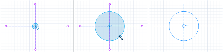
To resize the point node
- In the graphical editor, select the point node you want to resize.
-
Drag the square handle on the edge of the node until you reach the intended size, then release the handle.
- General
-
Name — The name of the node. The name is used to identify and access the node from the code.
Show name — If selected, the shape’s name is displayed on the graphical diagram.
Lock — If selected, the node shape is locked. Locked elements do not respond to mouse clicks, and they cannot be selected in the graphical editor until you unlock them. This is often needed when you want to prevent the element from being edited while other elements are placed over it.
Ignore — If selected, the node is excluded from the model.
Speed limit for transporters — If selected, limits transporter speed to the specified value. Applied instantly when a transporter reaches the node.
- Appearance
-
Color — The color of the node. Selecting No color will cause the node to be invisible.
- Position and size
-
Level — The level to which this element belongs.
X — The X-coordinate of the area’s start point.
Y — The Y-coordinate of the area’s start point.
Z — The Z-coordinate of the area, in meters. The value is relative to the Z-coordinate of the area’s level.
Radius — The radius of the point node.
- Visibility and presentation
-
Visible — If selected, the node is visible during animation at model runtime.
Show in — Select whether the shape is displayed in both 2D and 3D animation, 2D only, or 3D only.
Agent presentation — If selected, the node is also visible on the upper-level agent that hosts the agent containing this node.
You can dynamically modify shape properties at model runtime using the API.
- Position
-
Function Description double getX() Returns the X coordinate of the node (namely, the coordinate of its upper left corner). double getY() Returns the Y coordinate of the node (namely, the coordinate of its upper left corner). double getZ() Returns the Z coordinate of the node (namely, the coordinate of its upper left corner). Point getXYZ() Returns the (X, Y, Z) coordinates of the given point. - Level
-
Function Description Level getLevel() Returns the level on which this node is located. - Visibility
-
Function Description boolean isVisible() Returns true if the node is visible; returns false otherwise. void setVisible(boolean v) Sets the visibility of the node.
v — visibility. If v is true — the node is set to be visible, if it is false — not visible. - Color
-
Function Description Color getLineColor() Returns the color of the node, or null if the node has no color or is textured (in this case use getFillTexture() to get the node’s texture). Texture getLineTexture() Returns the texture of the node or null if the node has no texture or is colored (in this case use getLineColor() to get the node’s color). void setLineColor(Color lineColor) Sets the color of the node.
lineColor — the new color, if null, the node is not drawn.void setFillColor(Color fillColor) Sets the color (or Texture) of the node.
fillColor — the new color, if null, the node is not drawn. - Network
-
Function Description Network getNetwork() Returns the network this markup element belongs to or null if this element is not a part of a network. int getConnectionsCount() Returns the number of the node’s connections with other nodes. Path getConnection(int index) Returns the connection between this node and another node by the provided index.
index — the index of required connection in range (0, this.getConnectionsCount() - 1). - Removal
-
Function Description void remove() Removes the node from the presentation. If the node is not a part of the presentation, the function does nothing. Removal from the presentation does not necessarily mean removal from the model logic, as logical networks and routes may have been created prior to removal and survive.
-
How can we improve this article?
-