


Now we want to create a 3D animation for our model.
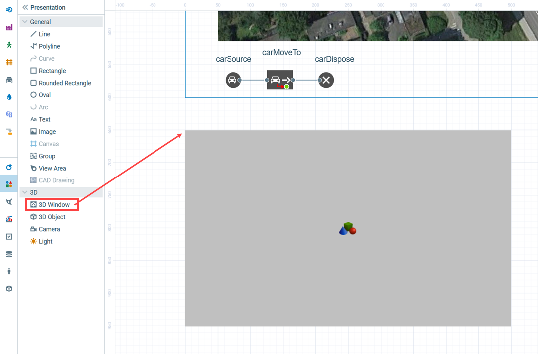
First of all, you should add a 3D Window to your Main diagram. The 3D window works as a placeholder for the 3D animation. It defines the area of the presentation diagram where the 3D animation will be shown at runtime.
Add a 3D window
- Drag the
 3D Window element from the 3D section of the Presentation palette to the graphical editor.
 -
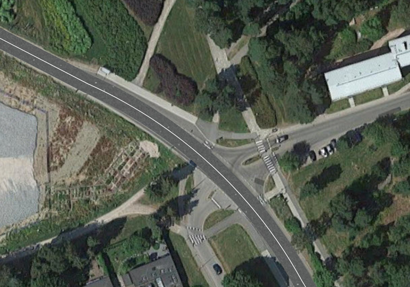
A grey area will appear. Place it where you want your 3D presentation to be shown at model runtime. In our model, the layout takes most of the space inside the model window (the blue rectangular frame you see in the graphical editor represents the borders of the model window). Let’s place the 3D window below the layout. To access the 3D animation during runtime, we will use a built-in AnyLogic navigation tool.
Now you can press Play and watch a simple 3D animation.
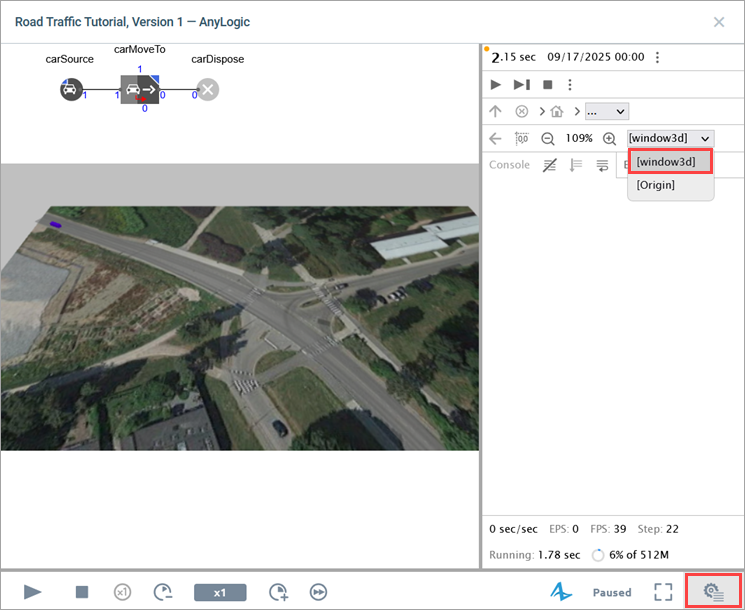
Navigating through the 3D animation
-
Run the model.
When you create a 3D window, AnyLogic adds a view area that allows you to easily navigate to the 3D view at runtime. To switch to this 3D view while the model is running, click the Developer panel control in the right corner of the control panel, expand the
  Select view area to navigate list and select [window3d].
-
You will see the 3D animation. By default, cars are shown as colored blocks.
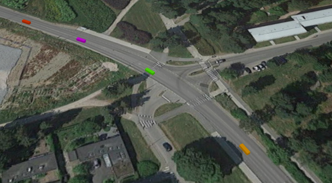
- Navigate through the 3D scene using the commands listed below.
| In order to | Use the mouse as described here |
|---|---|
| Move the scene | 1. In the 3D view, press and hold the left mouse button. 2. Move the mouse in the required direction. |
| Rotate the scene | 1. Press and hold the Alt key (macOS: Option key). 2. Keeping the Alt key pressed, click anywhere in the 3D window. 3. With both Alt key and the left mouse button pressed, move the mouse in the desired direction. |
| Zoom in/out the scene | 1. Scroll the mouse wheel in the 3D window away from/towards you (macOS: scroll while pressing the Ctrl or the Option key). |
Now we want to set a specific 3D animation shape for cars instead of the default one. This requires a custom car agent type.
Create a new car type
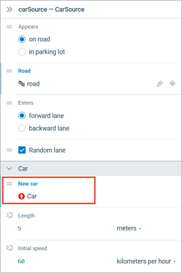
- To create a new type of car, select the carSource block on the Main graphical diagram.
- In the Car section of its properties, click the New car field.
- In the menu that appears, click Create new agent.
- The New agent type wizard appears. We will use the default Agent type name Car.
-
Under Animation shape, you can select one of the built-in shapes. By default, the Car shape is selected; leave it as it is for this type of agent.
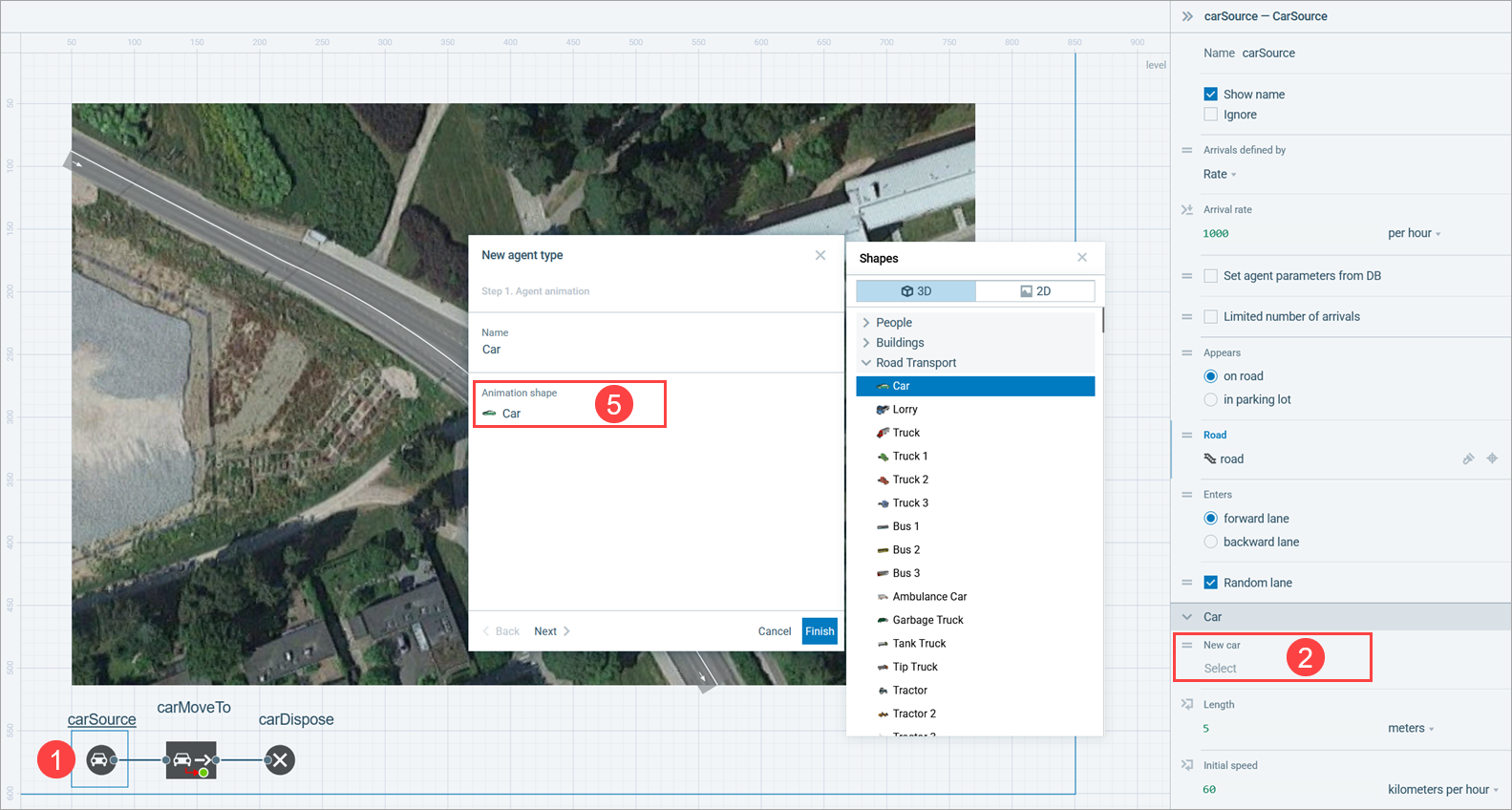
- Click Finish. A new agent type is created and its graphical diagram opens automatically.
Configure the flowchart to use the new car type
- On the Main graphical diagram, select the carSource block.
-
In the Properties view, expand the Car section and make sure
 Car is selected in the New car drop-down list.
-
Run the model and switch to the 3D view to see our 3D cars moving along the road.
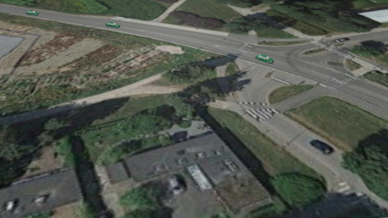
The color of our road is similar to the color of the road on the layout, which makes them merge. But as you can see, the road and the layout interlace sometimes. We need to make a few adjustments to prevent interlacing and make the animation look more appealing.
Change the background color of the drawn road network
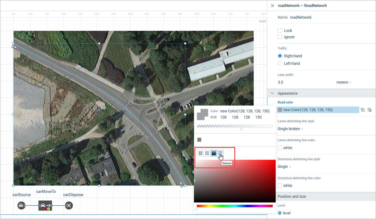
- Select the road network with two consecutive single-clicks on the road (the first click will select the road itself, while the second one will select the road network).
-
Open the Appearance section in the road network’s Properties. Click the Road color control, then select Textures.
-
In the Textures dialog box, select tarmac.
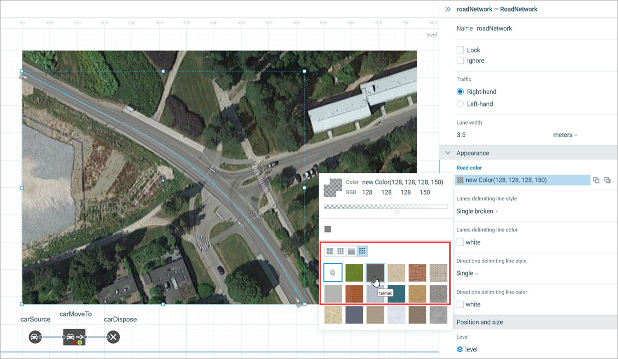
The drawn road will now differ in color from the road on the layout.
We still need to fix the interlacing issue that is visible in the 3D mode. The source of the problem is in the same Z-level of the road network and the layout image (0).
Adjust the Z-level of the image
- Click the layout image in the graphical editor.
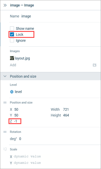
- Open the Position and size section of the layout’s properties and enter -1 as the Z value.
-
Select the Lock check box in the Properties view to fix the image in place. Locked shapes do not react to mouse clicks: it is impossible to select them in the graphical editor until you unlock them. Locking the image helps us prevent accidental image editing while drawing shapes over it.
Congratulations on completing the second phase! In the next phase, we will draw one more road and model the traffic flow on an automatically created intersection.
Demo model: Road Traffic Tutorial — Phase 2 Open the model page in AnyLogic Cloud. There you can run the model or download it (by clicking Model source files). Demo model: Road Traffic Tutorial — Phase 2Open the model in your AnyLogic desktop installation.-
How can we improve this article?
-